توفر المكابس المؤازرة الحديثة تحكمًا دقيقًا ومتسقًا في القوة. ومع ذلك، حتى الأنظمة المتقدمة يمكن أن تواجه مشاكل عند حدوث حمل زائد. يمكن أن يؤدي الحمل الزائد إلى تلف الأدوات أو ثني الإطارات أو التسبب في توقف الإنتاج بشكل غير متوقع. تؤدي هذه المشكلات إلى ارتفاع تكاليف الصيانة وإهدار الوقت، مما يؤثر بدوره على كل من السلامة والموثوقية.
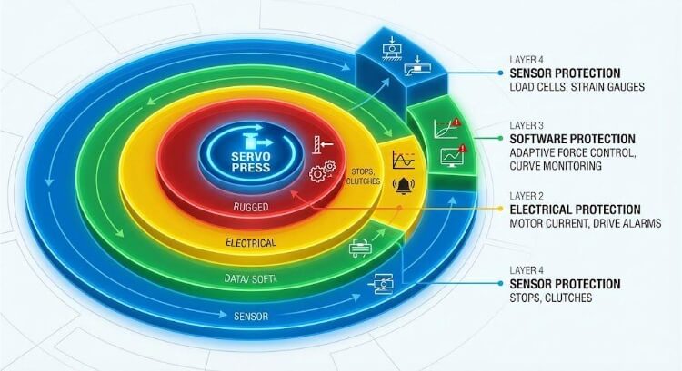
تستخدم المكابس المؤازرة أجهزة الاستشعار وأنظمة التحكم ومكونات السلامة الميكانيكية لمنع التلف قبل حدوثه. فهي تتعقب القوة والموضع في الوقت الفعلي وتوقف الكبش على الفور إذا تجاوز الحد المعين مسبقًا. تحافظ هذه الحماية الذكية على الأدوات في حالة جيدة، وتساعد على بقاء القِطع دقيقة وتدعم التشغيل السلس حتى عندما يتغير الحمل.
الحماية من التحميل الزائد أكثر من مجرد ميزة احتياطية. إنها جزء أساسي من تصميم المكبس الحديث. تشرح الأقسام التالية كيفية عمل هذه الأنظمة، والطرق الهندسية التي تجعلها موثوقة، وكيف تحافظ على ثبات الإنتاج في ظل الظروف الصعبة.

دور الحماية من الحمل الزائد في أنظمة المكبس المؤازر
عندما تنحشر عملية التثبيت بالضغط أو التشكيل فجأة في منتصف الشوط، فإن كل جزء من الثانية مهم. تضمن الحماية من التحميل الزائد مكابس مؤازرة تظل آمنة ودقيقة ومتسقة تحت ضغط التصنيع في العالم الحقيقي.
لماذا تحدث أحداث التحميل الزائد في العمليات الصحفية?
يحدث الحمل الزائد عندما تتجاوز القوة المطبقة السعة المقدرة للمكبس أو الأدوات. في الإنتاج اليومي، غالبًا ما تحدث أخطاء صغيرة، مثل الإعداد غير الصحيح، أو الحمولة غير المناسبة، أو التزييت غير الكافي. يمكن أن يؤدي القالب غير المحاذي إلى إزاحة الحمل عن المركز، بينما يمكن أن يتسبب وجود نتوء أو بقعة صلبة في الصفيحة في حدوث ارتفاع مفاجئ في القوة.
حتى الاختلاف الطفيف 5% في صلابة المواد يمكن أن يرفع قوة التشكيل بما يكفي لتحفيز التحميل الزائد. تستجيب المكابس المؤازرة بشكل أسرع من أي مشغل، ولكن لا تزال الوقاية تعتمد على المعايرة المناسبة والتغذية الثابتة للمواد. تساعد إدارة هذه العوامل الصغيرة ولكن الرئيسية في الحفاظ على إمكانية التنبؤ بالأحمال الزائدة والتحكم فيها.
المخاطر على الأدوات والآلات وجودة المنتج
يمتد تأثير الحمل الزائد إلى ما هو أبعد من مجرد أداة واحدة تالفة. يمكن أن تؤدي المثقاب المتصدع أو القالب المثني إلى اختلال محاذاة الأجزاء اللاحقة، مما يؤدي إلى انتشار المشكلة في جميع أنحاء الدفعة. كما تؤدي دورات التحميل الزائد المتكررة أيضًا إلى إجهاد إطار المكبس والمحامل والبراغي الكروية، مما يقلل الدقة ببطء بمرور الوقت.
بالنسبة للمنتج، يمكن أن يتسبب الضغط الزائد في حدوث تباين في الحجم أو تشققات أو تشطيب سطح رديء. في إحدى عمليات التدقيق في أحد المصانع، أدى التحميل الزائد غير المنضبط إلى ما يقرب من 301 تيرابايت في 3 تيرابايت من جميع أوقات تعطل المكابس غير المخطط لها على خطوط المؤازرة. إن منع التحميل الزائد لا يحمي المعدات فحسب، بل يحافظ أيضًا على استقرار جودة المنتج ووقت التشغيل.
الفرق بين الحمل الزائد المتحكم فيه وفشل النظام
يحدث الحمل الزائد المتحكم فيه عندما تكتشف المستشعرات ارتفاعًا في القوة وتتفاعل على الفور. يقوم النظام بإيقاف أو عكس الكبش وفك عزم الدوران ومنع حدوث ضرر دائم. يمكن استئناف الإنتاج بعد انقطاع قصير.
يحدث فشل النظام عندما يكون رد الفعل بطيئًا للغاية. يستمر الكبش في الحركة، مما قد يؤدي إلى إتلاف الأدوات أو إجهاد المحرك. يمكن أن يكون فرق التوقيت قصيرًا مثل 5-10 مللي ثانية - ولكن هذه الفجوة الصغيرة تقرر ما إذا كانت المكبس يتعافى أو يتعطل.

أساسيات سلوك الحمل والقوة في المكابس المؤازرة
تحدد الطريقة التي تتصرف بها القوة داخل مكبس مؤازر مدى دقة واتساق كل جزء. يمكّن فهم هذا الرابط المهندسين من ضبط معلمات المكبس وضبطها بمزيد من التحكم.
العلاقة بين القوة والضربة وملامح الحمل العادي
عندما يتحرك الكبش إلى أسفل، فإنه يبني قوة عندما يلمس المادة. إن منحنى القوة-الضربة يرتفع تدريجيًا حتى تبدأ المادة في التشوه، ثم يصل إلى الذروة وينخفض مرة أخرى أثناء التفريغ. يعمل هذا المنحنى بمثابة "بصمة" لعملية تشكيل مستقرة.
يشير المنحنى السلس والقابل للتكرار إلى أن العملية يتم التحكم فيها بشكل جيد - مع المحاذاة الصحيحة والتشحيم النظيف وعمق الشوط المناسب. على سبيل المثال، يمكن لمكبس مؤازر بوزن 5 كيلو نيوتن الحفاظ على إمكانية تكرار قوة ± 1 1 تيرابايت 3 تيرابايت ودقة موضع ± 0.01 مم على مدى آلاف الدورات. إذا لاحظ المهندسون وجود نتوءات أو انخفاضات في المنحنى، فهذه علامة مبكرة على تغير ظروف الاحتكاك أو المقاومة أو الإعداد.
الأسباب الشائعة لارتفاعات القوة غير الطبيعية
تظهر طفرات القوة عندما تواجه المكبس مقاومة أكثر من المتوقع. غالبًا ما تتسبب النتوءات أو سوء التشحيم أو الحطام الصغير على سطح القالب في حدوث هذه القفزات المفاجئة. يمكن أن تؤدي حواف المثقاب البالية أو عمق الضربة الزائد أو الأوساخ في منطقة التشكيل إلى حدوث مشكلات مماثلة.
عندما يحدث هذا، تكتشف المستشعرات ارتفاع القوة في غضون 5-8 مللي ثانية وترسل إشارة إلى نظام التحكم لإيقاف المكبس مؤقتًا أو سحبها. هذه الاستجابة السريعة توقف الضغط من الانتشار عبر الإطار أو المحامل. وبمرور الوقت، تساعد دراسة ارتفاعات القوة هذه المهندسين على اكتشاف التآكل المبكر للأدوات والتخطيط للصيانة ومنع الأحمال الزائدة في المستقبل.
تأثير اختلال المحاذاة وتباين المواد
حتى الاختلالات الصغيرة في المحاذاة يمكن أن تغير توزيع القوة عبر القالب. يمكن لكمة خارج المركز بمقدار 0.1 مم فقط أن تحمّل جانبًا واحدًا بما يصل إلى 30-40 % أكثر. يؤدي هذا الضغط غير المتساوي إلى تسريع التآكل ويمكن أن يؤدي إلى حدوث تشققات أو انحناءات طفيفة.
التغييرات المادية مؤثرة بنفس القدر. يمكن للصفائح الأكثر صلابة أو الطلاء الأكثر سمكًا أن يدفع منحنى القوة-الضربة بالكامل إلى أعلى. عند تكرار هذه التغييرات، يمكن أن تتسبب هذه التحولات في حدوث تحفيزات متكررة للحمل الزائد. للحفاظ على تشغيل المكبس بسلاسة، يجب على المهندسين إجراء فحوصات محاذاة القالب بانتظام، واستخدام موردي المواد المستقرة، ومراقبة بيانات القوة والضربة المباشرة بحثًا عن أي علامة على الانحراف.
طرق الحماية من الحمل الزائد الميكانيكية
تشكل الحماية الميكانيكية العمود الفقري لنظام سلامة المكبس المؤازر. عندما تفشل المستشعرات أو البرامج في الاستجابة في الوقت المناسب، تتولى الأجزاء الميكانيكية امتصاص أو منع القوة الإضافية.
التوقفات الميكانيكية وتصميم الحد الصلب
تحدد التوقفات الميكانيكية الحد الأقصى للمسافة التي يمكن أن تقطعها المكبس. فهي تمنعه فعليًا من التحرك إلى ما بعد نقطة آمنة، حتى إذا فشل نظام التحكم. وهذا يمنع القالب من الإغلاق بعيدًا جدًا أو الضغط على المادة بشدة.
تُصنع هذه التوقفات من الفولاذ المقوى وتوضع في المناطق الحاملة للإطار. وهي لا تحتاج إلى طاقة أو إشارة أو برامج - فقط الفحص المنتظم. في اختبار مكابس مؤازرة منضدية بوزن 3 كيلو نيوتن باستخدام نقاط توقف ميكانيكية في الموضع الصحيح، تم خفض تلف الأداة بأكثر من 401 تيرابايت 3 تيرابايت مقارنةً بالمكابس التي تعتمد على الحدود الإلكترونية فقط.
قوابض التحميل الزائد وأجهزة تحديد عزم الدوران
تضيف قوابض التحميل الزائد طبقة دفاعية داخل نظام الدفع. عندما يتجاوز عزم الدوران قيمة محددة مسبقاً، ينفصل القابض تلقائياً، ويفصل المحرك وعلبة التروس عن الكبش. وهذا يمنع القوة الزائدة من الوصول إلى الأجزاء الحرجة.
يمكن أن تكون محددات عزم الدوران الحديثة إلكترونية أو ميكانيكية بحتة. تتفاعل الإصدارات الإلكترونية بشكل أسرع ويعاد ضبطها تلقائيًا بمجرد عودة الحمل إلى الوضع الطبيعي. وهي شائعة في مكابس التجميع الدقيقة، حيث يمكن أن تؤدي التغيرات المفاجئة في عزم الدوران إلى تلف البراغي الكروية أو صواميل الإدارة.
هوامش السلامة الهيكلية في تصميم الإطار والقيادة
تم تصميم كل مكبس مؤازر بهامش أمان مدمج في هيكله. تم تصميم كل من الإطار والمحامل والبرغي اللولبي الكروي للتعامل مع حمولة تزيد بمقدار 20-30% عن السعة المقدرة لفترات قصيرة من الوقت. تساعد هذه القوة الإضافية المكبس على امتصاص الأحمال الزائدة القصيرة دون فقدان الشكل أو الدقة.
يستخدم المهندسون تحليل العناصر المحدودة (FEA) لدراسة كيفية توزيع الضغط في جميع أنحاء الإطار تحت الأحمال الثقيلة. تحافظ الزوايا المعززة والأعمدة الأكثر سمكاً ومسارات الأحمال المتوازنة على صلابة الإطار وثباته. يمكن للإطار المصمم بشكل جيد تحمل الأحمال الزائدة المؤقتة والعودة إلى المحاذاة المثالية بعد ذلك.
استراتيجيات الحماية الكهربائية والحماية على مستوى المحرك
تشكل الأنظمة الكهربائية وأنظمة مستوى القيادة خط الدفاع الثاني الأسرع ضد الحمل الزائد. تكتشف أدوات التحكم الإلكترونية هذه التغييرات في التيار أو عزم الدوران أو الموضع قبل أن تشعر الماكينة بأي ضغط حقيقي.
مراقبة تيار المحرك وحدود عزم الدوران
في المكبس المؤازر، يعكس تيار المحرك مباشرةً ناتج عزم الدوران. عندما يرتفع التيار بشكل حاد، فهذا يعني أن المكبس يواجه مقاومة غير متوقعة. تتفاعل وحدة التحكم على الفور عن طريق الحد من عزم الدوران أو إيقاف الحركة لتجنب الإجهاد الميكانيكي.
تعمل حلقة التغذية الراجعة هذه كأول جدار أمان رقمي. على سبيل المثال، إذا تعرض محرك 2 كيلو نيوتن لارتفاع تيار 15%، فإن النظام يقوم تلقائيًا بوضع حد أقصى لعزم الدوران للبقاء ضمن الحدود الآمنة. هذا يحمي المحرك، والبرغي اللولبي الكروي، والمحرك من إجهاد الحمل الزائد مع الحفاظ على التحكم الكامل في دقة الشوط.
ملاحظات أداة التشفير والضمانات القائمة على الموقع
تقوم أجهزة التشفير بتتبع حركة الكبش بدقة على مستوى الميكرون. وهي تقارن باستمرار الحركة المطلقة مع ملف تعريف الشوط المبرمج لاكتشاف المقاومة أو الانزلاق. إذا تجاوز الانحراف التفاوت المسموح به المحدد، يتوقف المكبس أو يتراجع على الفور لمنع حدوث تلف.
نظرًا لأن المكابس المؤازرة تعمل بسرعات متغيرة، يضمن تتبع الموضع هذا بقاء جميع الحركات متزامنة حتى في ظل الأحمال المتغيرة. في الاختبار، استجابت المكابس المزودة بأجهزة تشفير مزدوجة - واحدة على المحرك والأخرى على الكبش - بشكل أسرع بحوالي 251 تيرابايت 3 تيرابايت للأحمال الزائدة من الأنظمة التي تستخدم مستشعرًا واحدًا.
إنذارات المحرك ومنطق إيقاف التشغيل التلقائي
تحتوي المحركات المؤازرة الحديثة على إنذارات مدمجة تراقب التيار الزائد واختلال عزم الدوران ودرجة حرارة المحرك. عندما يتم تشغيل أحد هذه الإنذارات، يتوقف المحرك تلقائيًا أو يبطئ من سرعة المكبس بسلاسة، مما يمنع التأثير المفاجئ على الأدوات.
يتم تسجيل كل حدث إنذار لمراجعته لاحقًا. يمكن لفرق الصيانة استخدام هذا السجل للعثور على السبب الفعلي - مثل تآكل الأداة أو انحشار المواد أو خطأ في الإعداد - وضبط المعلمات حسب الحاجة. يؤدي هذا إلى تحويل الحماية من التحميل الزائد إلى أداة صيانة تنبؤية، مما يقلل من وقت التعطل غير المخطط له ويمكّن المكبس من العمل لفترة أطول مع عدد أقل من الأعطال.
منطق الحماية من التحميل الزائد والتحكم القائم على البرمجيات
تضيف الحماية القائمة على البرمجيات طبقة تنبؤية للتحكم في المكبس المؤازر. في حين أن الأنظمة الميكانيكية والكهربائية تتفاعل مع الأحمال الزائدة بعد حدوثها، تساعد البرمجيات على إيقافها قبل أن تبدأ.
إعدادات عتبة القوة والحدود التكيفية
تحدد كل وحدة تحكم في المكبس المؤازر عتبات القوة بناءً على الأدوات والمواد. عندما تقترب القوة المباشرة من هذه الحدود، يقوم البرنامج بإبطاء أو إيقاف ذاكرة الوصول العشوائي مؤقتًا لمنع التحميل الزائد. يحدث هذا الإجراء في غضون أجزاء من الثانية، مما يحافظ على العملية داخل نطاق آمن.
تأخذ الأنظمة المتقدمة خطوة إلى الأمام مع التحكم في الحد التكيفي. يقوم البرنامج تلقائيًا بضبط نطاق القوة المسموح به اعتمادًا على درجة الحرارة أو سرعة الشوط أو صلابة المادة. على سبيل المثال، عند تشكيل مادة أكثر ليونة، فإنه يخفض الحد المسموح به لمنع الضغط الزائد. يحافظ هذا الضبط الذكي على الدقة مع منع مشغلات التحميل الزائد الكاذبة.
مراقبة منحنى القوة - الإزاحة في الوقت الحقيقي
أثناء كل شوط، تقوم وحدة التحكم بتتبع منحنى إزاحة القوة ومقارنته بمرجع مثالي. يؤدي أي ارتفاع مفاجئ، أو انخفاض، أو إزاحة مفاجئة خارج نطاق التحمل إلى استجابة فورية للحمل الزائد.
يحذّر تتبع المنحنى في الوقت الحقيقي أيضًا المهندسين من تآكل الأداة أو تراكم الطلاء أو اختلال طفيف في المحاذاة. ويمكنهم استخدام هذه البيانات لضبط عمق الشوط أو الضغط قبل ظهور العيوب. تعرض العديد من الأنظمة الحديثة المنحنيات المباشرة والمرجعية جنبًا إلى جنب على واجهة إدارة الأدوات HMI، مما يتيح للمشغلين اكتشاف التغييرات على الفور.
الكشف عن الأعطال وتسلسلات الاسترداد التلقائي
عند حدوث حمل زائد، يقوم البرنامج بتشغيل تسلسل استرداد تلقائي. يسحب الكبش بأمان، ويحرر الضغط المحتجز، ويعيد ضبط إعدادات النظام. تقوم بعض المكابس بتوجيه المشغل خلال كل خطوة من خطوات الاسترداد على واجهة HMI حتى يمكن استئناف الإنتاج بسرعة.
تمنع هذه العملية حدوث المزيد من الضرر وتقلل من وقت التعطل. يتم تسجيل كل حدث من أحداث التحميل الزائد مع تفاصيل مثل الوقت والقوة وموضع الضربة للمراجعة المستقبلية. بمرور الوقت، تساعد هذه البيانات المهندسين على تحسين إعدادات المكبس والتنبؤ بالأعطال قبل حدوثها.
تقنيات الاستشعار التي تدعم الحماية من الحمل الزائد
تعطي المستشعرات مكبس المؤازرة وعيها في الوقت الحقيقي. فهي تقيس القوة والحركة والإجهاد أثناء كل شوط، مما يسمح للنظام بالتفاعل قبل حدوث أي ضرر.
تكامل خلايا التحميل ومقاييس الإجهاد
تقيس خلايا التحميل القوة المطبقة بدقة عند نقاط رئيسية في المكبس. وهي تستخدم مقاييس إجهاد تنثني قليلاً تحت الضغط، مما يؤدي إلى تغيير المقاومة الكهربائية. تقوم وحدة التحكم بتحويل هذه التغييرات إلى قراءات دقيقة للقوة يتم تحديثها آلاف المرات في الثانية.
توضع هذه الحساسات عادةً تحت الكبش أو في رأس المكبس لتسجيل أحمال التشكيل الحقيقية. يسمح وقت استجابتها - غالبًا ما يكون أقل من 5 مللي ثانية - لنظام التحكم بإيقاف الحركة أو عكسها قبل أن ينتشر الضغط عبر الإطار. تضمن المعايرة المنتظمة قراءات مستقرة وموثوقة على مدى الاستخدام الطويل.
مزايا القياس المباشر للقوة
يوفر القياس المباشر للقوة صورة أوضح من الاستشعار غير المباشر من خلال عزم الدوران أو التيار. فهو يعرض الضغط الفعلي عند واجهة القالب، حيث يبدأ تلف الحمل الزائد عادةً. تساعد هذه الدقة في اكتشاف حتى الارتفاعات الصغيرة في المقاومة الناجمة عن التآكل أو الحطام أو اختلال المحاذاة.
على سبيل المثال، إذا زادت قوة التشكيل بمقدار 10% ببطء، يمكن للنظام تنبيه المشغل قبل حدوث حمل زائد. يتيح نظام الإنذار المبكر هذا الصيانة الوقائية، ويساعد في الحفاظ على ثبات الإنتاج، ويطيل عمر الأداة من خلال تجنب الإجهاد غير الضروري.
وضع المستشعر وموثوقية الإشارة
يؤثر موضع المستشعرات بشكل مباشر على الدقة وسرعة الاستجابة. إذا كانت بعيدة جدًا عن ذاكرة الوصول العشوائي، تصبح الإشارات أضعف وأبطأ في الاستجابة. وللحصول على أفضل القراءات، عادةً ما يقوم المهندسون بتركيب الحساسات بالقرب من مسار القوة الرئيسي، عادةً بالقرب من رأس المثقاب أو لوحة القاعدة.
استقرار الإشارة مهم بنفس القدر. تساعد الكابلات المحمية والأسلاك التفاضلية ومرشحات الضوضاء على منع التداخل من المحركات ومصادر الضوضاء الكهربائية الأخرى. حتى أن بعض مكابس المؤازرة المتقدمة تستخدم مضخمات مدمجة لتقوية الإشارات المنخفضة.
خاتمة
تحدد الحماية من التحميل الزائد مدى أمان وكفاءة أداء مكبس المؤازرة على أرضية الإنتاج. إنه أكثر من مجرد نظام احتياطي - إنه نهج تصميم مدمج يربط بين القوة الميكانيكية والسرعة الإلكترونية والتحكم الذكي. عندما تتمكن المكبس المؤازر من اكتشاف الحمل غير الطبيعي، والتفاعل في غضون أجزاء من الثانية، والتعافي تلقائيًا، فإنها تثبت موثوقيتها الهندسية الحقيقية.
هل تريد تقليل وقت التعطل وحماية استثماراتك في المكبس المؤازر؟
تواصل مع فريقنا الهندسي لمراجعة شاملة للحماية الكاملة من التحميل الزائد. سنساعدك في العثور على نقاط الضعف واقتراح ترقيات عملية للحفاظ على عملياتك أكثر أمانًا واستقرارًا وإنتاجية.
الأسئلة الشائعة
ما هو السبب الأكثر شيوعًا للحمل الزائد في المكبس المؤازر؟
تحدث معظم الأحمال الزائدة بسبب أخطاء الإعداد أو الاختلافات في المواد. يمكن أن تؤدي الأدوات غير المحاذاة، أو حدود القوة غير الصحيحة، أو صلابة الصفيحة غير المتناسقة إلى حدوث ارتفاع مفاجئ في الحمل.
هل يمكن للحماية من التحميل الزائد المستندة إلى البرمجيات أن تحل محل الضمانات الميكانيكية؟
لا، تعمل البرمجيات على تحسين سرعة الكشف ولكنها لا يمكن أن تحل محل أجزاء السلامة الميكانيكية. لا يزال التوقف المادي ومحددات عزم الدوران هي الطبقة النهائية للحماية عندما تستجيب الأنظمة الإلكترونية ببطء شديد.
كيف تؤثر الحماية من الحمل الزائد على زمن الدورة والإنتاجية؟
بالكاد تؤثر الحماية المضبوطة جيدًا على زمن الدورة. بل إنها في الواقع غالبًا ما تزيد من وقت التشغيل عن طريق منع تآكل الأدوات، وتجنب الإصلاحات، والحفاظ على ثبات الإنتاج.
هل الحماية من التحميل الزائد ضرورية أيضًا للمكابس المؤازرة الصغيرة؟
نعم، عادةً ما تتعامل المكابس الصغيرة مع القِطع الدقيقة والمكونات الهشة. حتى الأخطاء الطفيفة في القوة يمكن أن تلحق الضرر بالأدوات أو المنتجات، لذا فإن الحماية المناسبة تضمن جودة ثابتة وقابلية التكرار.
كم مرة يجب مراجعة إعدادات الحماية من الحمل الزائد؟
راجع الإعدادات في أي وقت تقوم فيه بتغيير الأدوات أو المواد أو معلمات العملية. بالنسبة للإنتاج المستمر، يساعد فحص ومعايرة الحدود كل ثلاثة إلى ستة أشهر في الحفاظ على الدقة والموثوقية.
مهلا، أنا كيفن لي

على مدى السنوات العشر الماضية، كنت منغمسًا في أشكال مختلفة من تصنيع الصفائح المعدنية، وشاركت رؤى رائعة هنا من تجاربي عبر ورش العمل المتنوعة.
ابقى على تواصل
كيفن لي
لدي أكثر من عشر سنوات من الخبرة المهنية في تصنيع الصفائح المعدنية، وتخصصت في القطع بالليزر، والثني، واللحام، وتقنيات معالجة الأسطح. كمدير فني في شنغن، أنا ملتزم بحل تحديات التصنيع المعقدة ودفع الابتكار والجودة في كل مشروع.
الموارد ذات الصلة

الفولاذ المقاوم للصدأ المقاوم لبصمات الأصابع: كيف يعمل، وكيف تختار


