Controlar os erros comuns de conceção de chapas metálicas é uma das melhores formas de poupar tempo, reduzir o desperdício e produzir peças com bom desempenho. A conceção para a manufacturabilidade (DFM) desempenha um papel central neste processo. Assegura que todas as opções de design, desde a tolerância de dobragem à colocação de furos, apoiam o fabrico sem problemas em vez de criarem problemas no chão de fábrica.
Este guia destaca os desafios mais comuns que os engenheiros enfrentam e demonstra como aplicar os princípios DFM para os resolver. Cada secção - dobragem, integração de hardware, acabamento e muito mais - oferece diretrizes claras e práticas que ligam diretamente a intenção do design a resultados fabricáveis.
Ao aplicar o DFM numa fase inicial, pode evitar erros antes do início da produção, melhorar a consistência entre as peças e reduzir o dispendioso retrabalho. Os capítulos seguintes acompanham-no passo a passo nestas questões, fornecendo um caminho claro para projectos de chapa metálica mais inovadores, mais fiáveis e mais fáceis de fabricar.
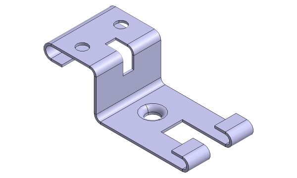
Evitar problemas comuns de dobragem
A dobragem pode parecer simples, mas as forças em ação podem causar problemas. Os projectistas têm de planear estes efeitos para obterem peças precisas.
Manuseamento do retorno elástico e da margem de curvatura
Primavera de volta ocorre quando o metal tenta voltar à sua forma plana original depois de ter sido dobrado. O exterior da folha estica mais do que o interior, e esta diferença faz com que a dobra relaxe um pouco. Por exemplo, as ligas de alumínio podem recuar 2-3 graus. Os aços de alta resistência podem recuar 5 graus ou mais. Para resolver este problema, os designers adicionam frequentemente uma pequena sobredobra para que a peça termine no ângulo correto.
Tolerância de dobragem é igualmente importante. Uma curva de 90 graus num aço laminado a frio de 1,5 mm pode acrescentar cerca de 2 mm ao comprimento do plano se não for tida em conta. Os projectistas utilizam tabelas de dobragem ou software para aplicar valores baseados em factores K. Estes variam normalmente entre 0,3 e 0,5 para a maioria das chapas metálicas. Sem estes números, mesmo uma peça pequena pode não encaixar onde é suposto.
Acrescentar relevos de curvatura
Os relevos de dobragem ajudam a impedir fissuras ou rasgões perto da linha de dobragem. Sem eles, a tensão acumula-se e pode levar o material a exceder o seu limite. As chapas mais espessas, especialmente as que têm mais de 2 mm, têm maior probabilidade de fissurar quando dobradas sem relevos. Um simples corte em relevo, aproximadamente tão largo como a chapa e ligeiramente mais comprido do que o raio de curvatura, resolve frequentemente o problema.
Os relevos também melhoram a precisão das peças. Em armários com curvas perto dos cantos, os cortes em relevo consistentes garantem que as dimensões se mantêm dentro de aproximadamente ±0,2 mm. Isto facilita a montagem e reduz o desalinhamento durante a soldadura ou fixação. Também reduz a necessidade de trabalho adicional numa fase posterior da produção.
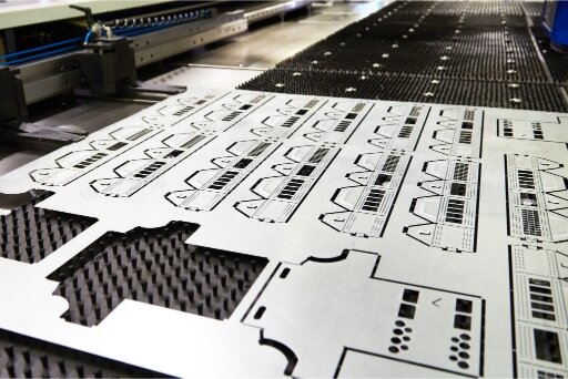
Conceção para corte e perfuração por laser
Corte a laser e perfuração Os modelos de design produzem resultados precisos, mas são mais eficazes quando o design segue algumas diretrizes importantes. Estas regras ajudam a manter as caraterísticas limpas e o processo fluido.
Escolher as dimensões e o espaçamento corretos dos furos
Os furos que são demasiado pequenos para a espessura do material são difíceis de cortar de forma limpa. Uma regra simples é manter um tamanho mínimo de furo que seja pelo menos igual à espessura da chapa. Por exemplo, em aço inoxidável de 2 mm, os furos mais pequenos do que 2 mm saem frequentemente cónicos ou incompletos.
O espaçamento entre furos é igualmente importante. Se os furos estiverem demasiado próximos, o calor do corte a laser ou a tensão da perfuração podem causar distorção. Uma diretriz padrão é manter um espaçamento de borda a borda de pelo menos 1,5 vezes a espessura da folha. Em alumínio de 3 mm, isto significa manter os orifícios afastados pelo menos 4,5 mm para garantir arestas limpas e peças estáveis.
Desenhar separadores e entalhes da forma correta
As patilhas proporcionam resistência em torno de recortes e ligam secções de uma peça. Se as abas forem demasiado estreitas, podem partir-se durante a dobragem ou o manuseamento. Uma regra segura é fazer com que a largura da aba seja pelo menos o dobro da espessura da chapa. Numa chapa de aço macio de 1,5 mm, isso significa que as patilhas devem ter pelo menos 3 mm de largura.
Os entalhes também necessitam de uma conceção cuidadosa. Os entalhes afiados criam pontos fracos que podem rachar durante o processo de conformação ou montagem. Uma boa abordagem é manter a profundidade do entalhe não superior a 1,5 vezes a espessura da chapa e arredondar sempre as extremidades em vez de deixar os cantos afiados. Por exemplo, numa chapa de 2 mm, um entalhe arredondado com 3 mm de profundidade tem muito menos probabilidades de fissurar do que um entalhe agudo.
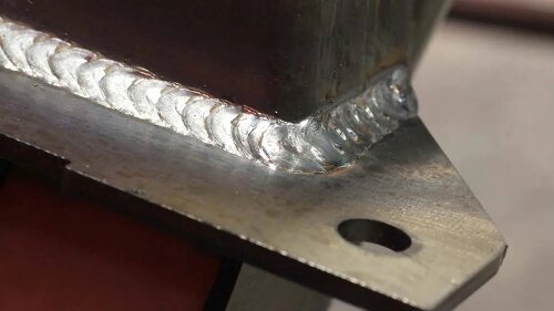
Garantir a soldabilidade e a montagem
As peças que são fáceis de soldar são normalmente mais fortes e mais fiáveis. As escolhas de design no ecrã têm um impacto direto na eficácia com que os soldadores podem realizar o seu trabalho.
Preparação de peças para soldaduras fortes
Bom soldaduras começar com a conceção correta da junta. Se as folgas forem demasiado grandes, a soldadura utiliza mais material de enchimento e acaba por ficar mais fraca. Se as folgas forem demasiado apertadas, a fusão pode não ser completa. Uma regra simples é manter as folgas das juntas entre 0,5 mm e 1 mm para a maioria das espessuras de chapa.
O estado da superfície também é importante. Óleo, revestimentos ou camadas de óxido bloqueiam a penetração adequada da soldadura. No alumínio, a camada de óxido pode aumentar o ponto de fusão da superfície em mais de 100°C em comparação com o metal de base. A especificação de passos de pré-limpeza, como o desengorduramento ou a aplicação de películas de proteção, ajuda a reduzir os defeitos de soldadura.
O acesso é outro fator fundamental. Se as flanges ou os reforços bloquearem a tocha, os soldadores não conseguem alcançar totalmente a junta. Deixar pelo menos 10 mm de espaço livre à volta das áreas de soldadura facilita o trabalho e garante uma força de soldadura consistente.
Conceção para controlar a distorção da soldadura
A soldadura aquece o material e o arrefecimento subsequente faz com que este se contraia de forma desigual. Isto causa frequentemente deformações, torções ou contração nas montagens. As chapas finas com menos de 2 mm são especialmente propensas à distorção, mesmo com cordões de soldadura curtos.
Os projectistas podem reduzir a distorção equilibrando as soldaduras em ambos os lados de uma peça. As soldaduras escalonadas, em vez de costuras longas e contínuas, também reduzem a entrada de calor, mantendo a resistência. Outro método útil é colocar as soldaduras perto do eixo neutro da peça, o que reduz as forças de flexão durante o arrefecimento.
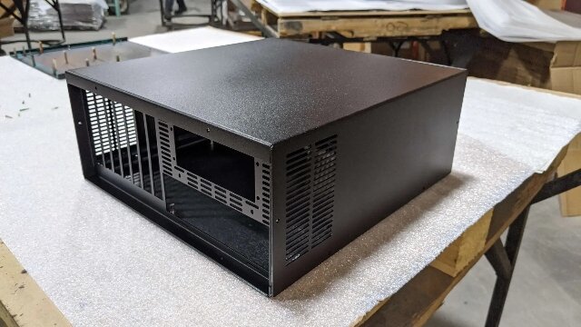
Conceção para integração de hardware
A adição de hardware diretamente à chapa metálica pode poupar tempo durante o processo de montagem. Um bom design garante que estes componentes permaneçam seguros e fiáveis durante a utilização.
Utilização de pastilhas PEM e pernos soldados
As pastilhas PEM proporcionam roscas fortes em chapas finas, onde não é possível efetuar roscas. Para que se mantenham firmes, o tamanho do furo deve corresponder rigorosamente às especificações da pastilha. Por exemplo, uma porca M4 PEM em aço de 1,5 mm necessita de um furo com uma tolerância de +0,08/0,00 mm. Mesmo um furo apenas 0,1 mm maior pode reduzir a força de retenção em mais de 20%.
A espessura da chapa também desempenha um papel importante. Uma porca auto-retrátil necessita normalmente de, pelo menos, 1 mm de material para se agarrar. As chapas mais finas podem deformar-se durante a instalação. Verificar a tabela de espessura mínima do fornecedor ajuda a evitar juntas fracas.
Os pernos soldados são outra opção de fixação forte. Funcionam bem quando as peças têm de suportar cargas elevadas. Um perno de 6 mm em aço macio de 2 mm pode atingir forças de tração superiores a 5 kN se a superfície estiver limpa e plana. A adição de uma pequena saliência ou almofada elevada no design melhora a penetração da soldadura e ajuda a manter o perno alinhado.
Construção de conjuntos fiáveis de porcas e parafusos prisioneiros
As porcas e os parafusos cativos mantêm-se fixos à peça mesmo quando soltos. Isto facilita a manutenção e reduz o risco de perda de hardware. Mas caraterísticas de retenção fracas podem fazer com que os fixadores girem ou se soltem.
Para porcas cativas, a profundidade da bolsa de retenção deve ser pelo menos 1,5 vezes a espessura da porca. Num painel de 3 mm, uma porca de aperto M5 standard pode suportar valores de binário superiores a 8 Nm sem deslizar. Os cantos arredondados da bolsa distribuem a tensão e melhoram a durabilidade.
Os parafusos de cabeça cilíndrica necessitam de espaço suficiente para se moverem livremente, mas não tanto que façam barulho. Uma folga de 0,2-0,3 mm à volta do corpo do parafuso funciona normalmente bem. Nos invólucros electrónicos, esta tolerância assegura que os parafusos permanecem seguros, permitindo a sua utilização repetida durante a manutenção.
A importância do acabamento no DFM
O acabamento protege a peça e melhora o seu aspeto. As escolhas de design corretas tornam os revestimentos mais consistentes e fiáveis.
Conceber uma boa preparação da superfície
A preparação da superfície tem um efeito direto na forma como os revestimentos aderem ao metal. O óleo, as rebarbas e os salpicos de soldadura bloqueiam a aderência. Os testes mostram que as superfícies sujas podem reduzir a resistência do revestimento em pó em mais de 30%. Os projectistas podem ajudar, evitando cantos apertados com larguras inferiores a 1 mm, uma vez que as ferramentas de jato de areia não os conseguem limpar eficazmente.
A planura também é importante. Painéis ondulados ou áreas deformadas podem causar revestimentos, tais como anodizaçãoA anodização pode fazer com que a superfície do alumínio pareça irregular. Nas chapas de alumínio, mesmo um desvio de 0,3 mm em 300 mm pode criar estrias visíveis após a anodização. Reforçar as nervuras ou manter uma espessura uniforme reduz a distorção, ajudando a manter a superfície plana.
Prevenção de problemas no revestimento em pó e na anodização
Revestimento em pó normalmente acrescenta uma espessura de 60-120 microns. Isto pode parecer pouco, mas pode alterar o encaixe. Por exemplo, um orifício de 6 mm pode encolher 0,1-0,2 mm após o revestimento, o que é suficiente para impedir o encaixe de um fixador. Adicionar folga ou chamar a atenção para a máscara garante que as dimensões estão corretas.
Os revestimentos também podem ficar presos. Os orifícios cegos, as ranhuras profundas ou os espaços fechados podem acumular pó em excesso ou líquido de anodização. Quando estas áreas curam ou secam, é frequente descamarem ou enfraquecerem. Os projectistas podem evitar esta situação adicionando orifícios de drenagem ou ventilação.
Criar um fluxo de trabalho centrado no DFM
Um fluxo de trabalho sólido liga diretamente as escolhas de design à forma como as peças são fabricadas. Quando o DFM é integrado nos processos diários, os projectos avançam mais rapidamente e os resultados são mais previsíveis.
Construir a colaboração entre a conceção e o fabrico
As equipas de conceção e fabrico olham frequentemente para as peças de ângulos diferentes. Os engenheiros concentram-se na função, enquanto os fabricantes lidam com as ferramentas e os limites do processo. A colaboração precoce ajuda a colmatar esta lacuna e evita erros antes de as peças chegarem à fase de produção.
As revisões regulares do projeto são um método simples. As verificações semanais entre as equipas de projeto e de produção podem reduzir o retrabalho. Os fabricantes podem identificar problemas como raios que não podem ser dobrados ou acesso de soldadura bloqueado, enquanto os engenheiros garantem que a intenção do projeto permanece intacta.
As ferramentas partilhadas também ajudam. Os sistemas CAD com dados de fabrico incorporados, tais como bibliotecas de deduções de dobras ou limites de ferramentas de punção, fornecem a ambos os grupos uma referência padrão. Isto assegura que os ficheiros de design estão alinhados com as capacidades reais da fábrica.
Utilização de uma lista de verificação de projeto para chapas metálicas
Uma lista de verificação é uma forma fiável de detetar erros antes de serem lançados. Embora cada projeto possa ter necessidades únicas, alguns itens aplicam-se a quase todos os projectos de chapa metálica.
Pontos-chave a incluir:
- Confirmar se os raios de curvatura correspondem às ferramentas disponíveis.
- Assegurar que os diâmetros dos furos são pelo menos iguais à espessura da folha.
- Deixar espaço livre para as ferragens e os revestimentos.
- Acrescentar relevos nas curvas e entalhes.
- Definir as tolerâncias com base na capacidade real de fabrico.
As listas de verificação ajudam a manter a consistência do design e minimizam o risco de detalhes negligenciados. Na prática, as equipas que as utilizam têm frequentemente prazos de entrega mais curtos e rendimentos mais elevados na primeira passagem.
Mesmo os projectos de chapa metálica bem planeados podem encontrar problemas se o DFM não for considerado desde o início. A aplicação dos princípios DFM ajuda-o a criar peças que são mais fáceis de fabricar, montadas de forma fiável e com um desempenho consistente no terreno.
Para obter apoio adicional, pode partilhar os seus ficheiros CAD com a nossa equipa. Analisaremos o seu projeto, forneceremos recomendações práticas de DFM e ajudaremos a optimizá-lo para uma produção mais suave.
Olá, chamo-me Kevin Lee

Nos últimos 10 anos, tenho estado imerso em várias formas de fabrico de chapas metálicas, partilhando aqui ideias interessantes a partir das minhas experiências em diversas oficinas.
Entrar em contacto
Kevin Lee
Tenho mais de dez anos de experiência profissional no fabrico de chapas metálicas, especializando-me em corte a laser, dobragem, soldadura e técnicas de tratamento de superfícies. Como Diretor Técnico da Shengen, estou empenhado em resolver desafios complexos de fabrico e em promover a inovação e a qualidade em cada projeto.
Recursos relacionados

Texturização a laser de metais: preparação, DFM e controlo de custos


Puncionamento vs corte a laser: Custo, velocidade e vantagens DFM
