Nauwkeurige bochten in plaatmetaal kunnen je project maken of breken. De buigtoeslag beïnvloedt de afmetingen van onderdelen, het materiaalgebruik en de assemblage. In deze gids lees je wat buigtoeslag is, waarom het belangrijk is en hoe je het kunt gebruiken voor betere resultaten.
Om duidelijk te begrijpen hoe bochtentoeslag werkt, moeten we kijken naar de belangrijkste factoren die het beïnvloeden. We moeten ook eenvoudige manieren bekijken om het te berekenen. Laten we tot slot een paar praktische voorbeelden bekijken. Dit zal ons helpen om elke keer weer nauwkeurige bochten te maken.
Wat is de bochtentoeslag in Plaatwerk Fabricage?
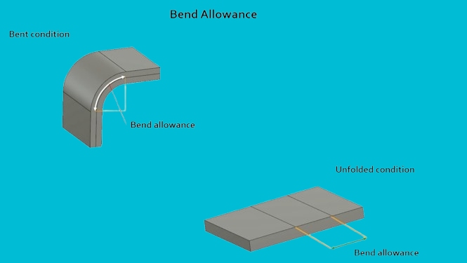
De buigtoeslag is de gebogen lengte metaal tussen de buiglijnen. Het vertelt je hoeveel materiaal er nodig is in het buiggebied. Wanneer metaal buigt, rekt het iets uit aan de buitenkant en drukt het samen aan de binnenkant. De buigtoeslag meet die verandering.
De toeslag is afhankelijk van factoren zoals materiaalsoort, dikte, buighoek en binnenradius. Elke bocht in een onderdeel voegt lengte toe en als je dat negeert, krijg je verkeerde maten. Door de buigtoeslag te berekenen, kun je het vlakke patroon aanpassen voordat je gaat buigen. Dit helpt ervoor te zorgen dat het afgewerkte onderdeel er goed uitziet.
De wetenschap achter buigtoelage
Om nauwkeurig plaatstaal te kunnen buigen, moet je weten wat er in het materiaal gebeurt. Deze veranderingen beïnvloeden de vorm, lengte en pasvorm van het uiteindelijke onderdeel.
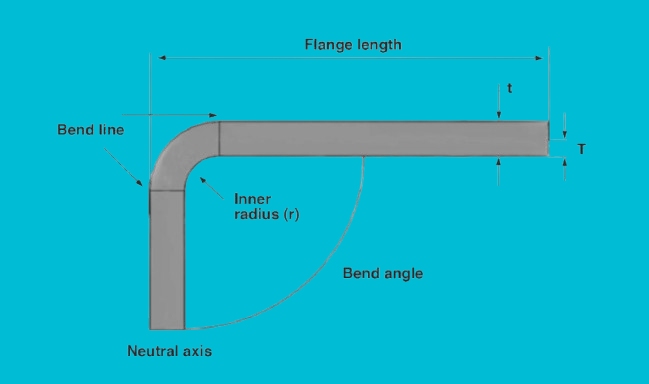
Buiglijn en neutrale as uitgelegd
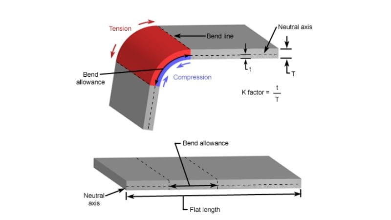
De buiglijn geeft het begin van de bocht aan. Aan de ene kant van deze lijn drukt het metaal samen. Aan de andere kant rekt het uit. Daartussen ligt de neutrale as. Deze lijn blijft dezelfde lengte, zelfs als het metaal buigt.
Voor de meeste bochten verschuift de neutrale as naar de binnenkant van de bocht. Hij is niet gecentreerd. In een 90° bocht op 1,0 mm dik staal zit de neutrale as bijvoorbeeld vaak ongeveer 0,4 mm van het binnenoppervlak. Die waarde verandert met het materiaaltype en de buigradius.
K-factor en de rol ervan bij het berekenen van de doorbuigingstolerantie
De K-Factor bepaalt waar de neutrale as ligt. Het wordt berekend met deze formule:
K = t / T
- t = afstand van het binnenoppervlak tot de neutrale as
- T = materiaaldikte
Veel voorkomende K-Factor waarden:
- Zacht aluminium (5052-H32): 0,33 tot 0,42
- Koudgewalst staal (SPCC): 0,40 tot 0,50
- Roestvrij staal (304): 0,45 tot 0,50
- Titaan graad 2: 0,30 tot 0,35
Laten we zeggen dat je werkt met 2 mm dik koudgewalst staal en dat je gemeten K-factor 0,45 is. De neutrale as zit 0,9 mm van het binnenoppervlak. Deze gegevens zorgen ervoor dat de berekening van de lengte van het vlakke patroon nauwkeurig blijft.
Belangrijkste factoren die de bochttoelage beïnvloeden
Verschillende factoren beïnvloeden hoeveel materiaal er nodig is voor een bocht. Elke factor verandert hoe metaal uitrekt en samendrukt tijdens het vormen.
Materiaalsoort en de invloed ervan
Verschillende metalen rekken op verschillende manieren uit. Zachtere materialen zoals aluminium buigen gemakkelijker en vereisen minder kracht. Hardere metalen zoals roestvrij staal hebben meer kracht nodig en kunnen terugveren meer na het buigen.
Aluminium 5052 buigt bijvoorbeeld gemakkelijk en gebruikt vaak een lagere buigtoeslag. Roestvrij staal 304 heeft meer weerstand tegen buigen en vereist een grotere buigradius om scheuren te voorkomen. De vervormbaarheid en treksterkte van het materiaal bepalen hoe het reageert onder druk.
Als je staal met een hoog koolstofgehalte buigt, moet je meer toeslag toevoegen om overbuiging of vervorming van het onderdeel te voorkomen. Houd altijd rekening met de mechanische eigenschappen van het metaal.
Dikte van de metalen plaat
Dikkere platen rekken meer uit tijdens het buigen. Naarmate de dikte toeneemt, wordt het buiggebied langer. Dit betekent dat er een grotere buigtoeslag nodig is.
Voor een 3 mm dikke staalplaat die onder een hoek van 90° is gebogen, is bijvoorbeeld een langere buigtoeslag nodig dan voor een plaat van 1 mm onder dezelfde hoek en met dezelfde radius. Hier is een algemene regel: als de dikte toeneemt, neemt ook de buigtoeslag toe.
Een dikkere plaat verschuift de neutrale as ook verder van het binnenoppervlak. Dat heeft direct invloed op de K-factor en maakt het vlakke patroon langer. Meet of bereken altijd op basis van de werkelijke dikte.
Krommingsstraal en de betekenis ervan
De buigradius is de binnenbocht van de bocht. Een kleine radius rekt het buitenoppervlak meer uit, waardoor de buigtoeslag groter wordt. Een grotere radius veroorzaakt minder uitrekking en heeft minder speling nodig.
Voor het buigen van 1,5 mm staal met een radius van 1,5 mm is bijvoorbeeld meer buigtoeslag nodig dan voor het buigen van dezelfde plaat met een radius van 3 mm. Kleine radii riskeren scheuren, vooral in harde materialen.
Een goede gewoonte is om de buigradius af te stemmen op de plaatdikte. Voor zacht staal is een straal gelijk aan de materiaaldikte (1T) meestal veilig. Voor aluminium kun je vaak kleiner gaan, maar voor roestvast staal kun je een radius van 1,5T of meer overwegen.
Buighoek en invloed op de tolerantie
De buighoek is hoe ver de plaat gebogen is, gemeten in graden. Hoe scherper de hoek, hoe meer het metaal uitrekt. Grotere buighoeken hebben dus meer speling nodig.
Een 90° bocht vereist meer materiaal in de buigzone dan een 45° bocht. Een 135° bocht rekt nog meer uit en heeft een langere vlakke lay-out nodig. Hier is een snelle vergelijking met een staalplaat van 1 mm met een radius van 1 mm:
- 45° bocht ≈ 1,1 mm toeslag
- 90° bocht ≈ 1,6 mm toeslag
- 135° bocht ≈ 2,4 mm toeslag
Hoe groter de hoek, hoe meer het vlakke patroon moet compenseren voor materiaalrek.
Formules en berekeningen voor buigtoelagen
Om een nauwkeurig vlak patroon te maken, moet je de buigtoeslag correct berekenen. Dit gedeelte laat zien hoe je dat stap voor stap doet.
Inleiding tot de bochtentoeslagformule
De meest gebruikte formule voor buigtoeslag is:
BA = (π × A × (R + K × T)) / 180
Waar:
- BA = Buigtoelage
- π = 3.1416
- A = buighoek in graden
- R = binnenste buigstraal
- T = materiaaldikte
- K = K-factor (afhankelijk van materiaal en opstelling van de bocht)
Deze formule geeft de booglengte van de neutrale as, die je optelt bij de vlakke lengte om nauwkeurige resultaten te krijgen.
Stap voor stap berekeningsproces
Laten we een voorbeeld bekijken.
Materiaal: Aluminium 5052-H32
Dikte (T): 2 mm
Binnenstraal (R): 2 mm
Buighoek (A): 90°
K-Factor: 0,38
Stap 1: Steek de waarden in de formule
BA = (3,1416 × 90 × (2 + 0,38 × 2)) / 180
Stap 2: Bereken de neutrale asterm
2 + (0.38 × 2) = 2.76
Stap 3: Vermenigvuldigen
3.1416 × 90 × 2.76 = 779.06
Stap 4: Verdelen
779,06 / 180 = 4,33 mm
De buigtoeslag is 4,33 mm. Dit voeg je toe aan je platte patroon om rekening te houden met buigen.
Veelvoorkomende fouten die je moet vermijden in berekeningen
- Verkeerde K-Factor: Het gebruik van een algemene gok kan leiden tot problemen met de afmetingen. Gebruik altijd geteste of aanbevolen waarden voor je specifieke materiaal en opstelling.
- De werkelijke dikte negeren: Als je vel gecoat of verkeerd gemeten is, heeft zelfs een klein verschil invloed op het resultaat.
- Onjuiste straal: Het gebruik van de gereedschapsradius in plaats van de werkelijke buigradius kan tot fouten leiden. Meet de gevormde bocht als u het niet zeker weet.
- Verwarrende buighoek: Meet altijd de inbegrepen hoek. Haal binnen- en buitenhoeken niet door elkaar.
- Het resultaat niet afronden: Gebruik één decimaal bij het afronden van buigtoeslagen. Te veel of te weinig kan leiden tot inconsistenties in de productie.
Rekenmachine voor buigtoelage
Bochttoelage vs. Bochtaftrek
Deze twee methoden helpen je om de vlakke lengte voor een gebogen onderdeel te plannen. Beide zijn nuttig, maar ze worden op verschillende manieren gebruikt.
Belangrijkste verschillen en wanneer ze te gebruiken
Buigtoelage (BA) is de booglengte van de bocht, gemeten langs de neutrale as. Je telt deze op bij de totale vlakke lengte. Het wordt gebruikt als je de buighoek, straal en K-factor weet.
Buigaftrek (BD) is het bedrag dat je aftrekt van de totale flenslengtes om het vlakke patroon te krijgen. Het is gebaseerd op dezelfde bocht, maar het gebruikt buitenmetingen.
Gebruik Buigtoelage wanneer je rekent vanaf de binnenkant van de bocht of wanneer je wilt werken met bekende radius- en materiaalwaarden. Het geeft je meer controle in CAD of CNC software.
Gebruik Bocht aftrek wanneer je het onderdeel meet van buiten naar buiten, vooral in handmatige lay-outs of eenvoudige platte patroontekeningen. Het wordt vaak gebruikt bij kantpersen waar de flenslengtes bekend zijn.
Beide leiden uiteindelijk tot dezelfde vlakke lengte, alleen vanuit verschillende startpunten.
Hoe om te rekenen tussen bochttoelage en bochtaftrek?
Je kunt met deze formule omrekenen tussen Bochttoelage en Bochtaftrek:
BD = FL1 + FL2 - BA - Totale lengte van het vlak
Maar voor de meeste toepassingen wordt deze eenvoudigere versie gebruikt:
BD = FL1 + FL2 - Vlakke lengte
Of, meer algemeen:
Platte lengte = FL1 + FL2 - BD
Waar:
- FL1 en FL2 zijn flenslengtes
- BD is de bochtaftrek.
- BA is de buigtoeslag.
Hier is een snel voorbeeld:
- FL1 = 30 mm
- FL2 = 40 mm
- BA = 4,33 mm
Dan:
Platte lengte = 30 + 40 - Bochtaftrek
of
Platte lengte = 30 + 40 + BA - 2 × buitenste terugstand
De keuze tussen BA en BD hangt af van hoe je je werkstukken meet en ontwerpt. Gebruik wat past bij je gereedschapopstelling of CAD-proces.
Beste praktijken voor optimale doorbuiging
De juiste buigtoeslag zorgt voor een betere pasvorm, minder uitval en een vlottere productie. Hier zijn manieren om uw buigingen nauwkeurig en herhaalbaar te houden.
Tips voor consistent en nauwkeurig buigen
- Gebruik dezelfde tools: Blijf bij dezelfde pons- en matrijzenset tijdens de productie. Verandering van gereedschap beïnvloedt de buigradius en de resultaten.
- Standaard K-factoren instellen: Gebruik geteste K-factoren voor elk materiaal en elke dikte. Gebruik bijvoorbeeld 0,38 voor aluminium 5052 en 0,44 voor zacht staal.
- Buig loodrecht op de nerf: Buigen langs de nerf leidt tot meer scheuren. Buig waar mogelijk dwars op de nerf.
- Vermijd scherpe radii: Gebruik een buigradius die gelijk is aan ten minste 1x de materiaaldikte voor zuivere resultaten, tenzij het ontwerp anders vereist.
- Gereedschap schoon houden: Vuil en versleten gereedschap zorgen voor inconsistente bochten.
- Controleveer terug: Gebruik onder- of bovenfrezen voor zeer nauwkeurige onderdelen waarbij de terugvering minimaal moet zijn.
Hoe uw berekeningen voor buigtoeslagen valideren?
- Testbochten maken: Knip een korte strook en maak een bocht. Meet het werkelijke resultaat en vergelijk het met je vlakke lay-out. Pas indien nodig de K-factor aan.
- Controleren aan de hand van CAD-uitvoer: Gebruik de berekende vlakke lengte om een CAD-tekening te maken. Buig een proefstuk en vergelijk het met het CAD-onderdeel.
- Meet de neutrale as handmatig: Gebruik een schuifmaat om te meten vanaf de binnenbocht tot de middellijn van de boog. Bereken de werkelijke K-factor en werk je formules bij.
- Herhaalde taken bijhouden: Houd de buigresultaten van repeterende onderdelen bij. Gebruik deze gegevens om toekomstige berekeningen te verfijnen.
- De herziening vormde onderdeeltoleranties: Als de positie van de gaten of de lengte van de flenzen niet klopt, kan dit wijzen op de verkeerde buigtoeslag. Pas dit dienovereenkomstig aan.
Het volgen van een paar herhaalbare stappen helpt om vallen en opstaan te verminderen. Als je eenmaal je instellingen hebt ingesteld, blijven de resultaten betrouwbaar in verschillende batches.
Conclusie
Buigtoeslag is de extra lengte in het vlakke patroon om rekening te houden met de rek van het materiaal tijdens het buigen. Het helpt ervoor te zorgen dat het afgewerkte onderdeel de juiste maat en vorm heeft. Factoren zoals materiaalsoort, dikte, buighoek, buigradius en de K-factor hebben allemaal invloed op de toeslag.
Hulp nodig bij het nauwkeurig buigen van plaatwerk of prototypen? Onze ingenieurs staan klaar om uw volgende project te ondersteunen. Neem contact met ons op voor een gratis advies of offerte.
Hey, ik ben Kevin Lee

De afgelopen 10 jaar heb ik me verdiept in verschillende vormen van plaatbewerking en ik deel hier de coole inzichten die ik heb opgedaan in verschillende werkplaatsen.
Neem contact op
Kevin Lee
Ik heb meer dan tien jaar professionele ervaring in plaatbewerking, gespecialiseerd in lasersnijden, buigen, lassen en oppervlaktebehandelingstechnieken. Als technisch directeur bij Shengen zet ik me in om complexe productie-uitdagingen op te lossen en innovatie en kwaliteit in elk project te stimuleren.
Verwante bron

Vingerafdrukbestendig roestvrij staal: hoe het werkt en hoe te kiezen

OEM vs Loonproductie: Hoe het juiste model voor uw project te kiezen

Setupkosten vs eenheidskosten bij de productie van plaatmetaal
