Als je plaatwerkonderdelen niet buigen zoals gepland, kan dat alles in de war sturen: uitlijning van gaten, afmetingen en uiteindelijke montage. Dat gebeurt meestal omdat de K-factor niet klopt. Het heeft invloed op hoe vlakke patronen worden berekend en hoe het afgewerkte onderdeel eruitziet. Als je niet de juiste K-factor gebruikt, krijg je gebogen onderdelen die niet overeenkomen met je model of tekening.
De K-factor is een getal dat aangeeft waar de rek plaatsvindt tijdens het buigen. Het geeft aan hoe ver de neutrale as in de plaat beweegt. Wanneer je een plaat buigt, rekt de buitenkant uit en drukt de binnenkant samen. De K-factor zit daar tussenin. Hiermee kun je berekenen hoeveel materiaal je nodig hebt voor nauwkeurige vlakke patronen. Als de K-factor verkeerd is, zal je onderdeel niet buigen zoals je gepland had.
Als je een betere pasvorm, nauwere toleranties en minder verrassingen wilt, moet je op dit getal letten.
Wat is de K-factor in plaatmetaal?
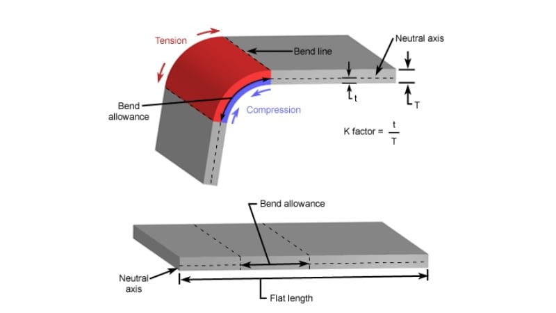
De K-factor is de verhouding die aangeeft waar de neutrale as zich bevindt binnen de dikte van het metaal tijdens het buigen. Wanneer metaal buigt, wordt de bovenkant samengedrukt en de onderkant uitgerekt. Ergens tussen deze twee krachten ligt een lijn die niet van lengte verandert. Dit is de neutrale as.
De K-factor drukt de verhouding uit tussen de offset van de neutrale as (t) en de materiaaldikte (MT). Deze berekening is van vitaal belang omdat ze beïnvloedt hoe het plaatwerk wordt verwerkt, gebogen en gesneden om aan de precieze specificaties te voldoen. De afbeelding hieronder laat zien hoe de bocht aan de bovenkant wordt samengedrukt en aan de onderkant wordt uitgerekt.

De wetenschap achter de K-factor van plaatmetaal
Als je metaal buigt, wordt het binnenoppervlak samengedrukt. Het buitenoppervlak rekt uit. Ergens daartussen ligt een lijn die niet van lengte verandert. Die lijn is de neutrale as.
De K-factor vertelt je waar die lijn zit als fractie van de totale dikte. Een K-factor van 0,5 betekent dat hij in het midden zit. Een K-factor van 0,3 betekent dat hij dichter bij de binnenkant zit.
De exacte positie hangt af van het materiaal, buigradiusen buigmethode.
Hoe beïnvloedt de K-factor het buigen van plaatmetaal?
Als je K-factor verkeerd is, zal je vlakke patroon verkeerd zijn. Dat leidt tot gaten op de verkeerde plekken, randen die niet op elkaar aansluiten of onderdelen die niet passen.
Een lage K-factor maakt het vlakke patroon langer. Een hoge K-factor maakt het korter. Als je dit getal goed hebt, krijg je precieze onderdelen zonder nabewerking.
De relatie tussen de K-factor en de neutrale as
De neutrale as verschuift afhankelijk van hoe het metaal buigt. Scherpere bochten en hardere metalen verschuiven naar binnen.
De K-factor geeft aan hoe ver die as zich van het binnenoppervlak bevindt. Als je de locatie van de neutrale as weet, kun je het volgende berekenen Buigtoelage en buigaftrek. Dat helpt je om onderdelen te ontwerpen die overeenkomen met wat uit de afkantpers.
K-factor berekenen
Als je de juiste K-factor weet, krijg je nauwkeurige vlakke patronen en hoef je minder te proberen bij de fabricage. Laten we eens uitleggen hoe de factor wordt berekend en wat hij onthult over je materiaal.
Hoe de K-factor berekenen?
Je kunt de K-factor berekenen met een formule die de buigtoeslag, buighoek, materiaaldikte en binnenradius omvat. De vergelijking is:
K = (180° × BA) / (π × θ × T) - (Ri / T)
Waar:
- K is de K-factor
- BA is de buigtoeslag
- θ de buighoek in graden is
- T de materiaaldikte
- Ri de straal van de binnenbocht is
Zodra je deze waarden hebt, stop je ze in de formule. Dit geeft je de K-factor, die aangeeft hoe ver de neutrale as van het binnenste buigoppervlak ligt, als fractie van de plaatdikte.
Om de werkelijke positie van de neutrale as te vinden, vermenigvuldig je de K-factor met de materiaaldikte:
t = K × T
K-Factor Rekenmachine
K-factor formule en geometrie uitgelegd
De K-factor komt van hoe metaal zich gedraagt als het in een boog wordt gebogen. De buiging vormt een cirkelvorm met een specifieke straal. Terwijl de buitenkant uitrekt en de binnenkant samendrukt, blijft de neutrale as even lang.
De booglengte van de neutrale as wordt gebruikt om de buigtoeslag te berekenen. De positie van deze as in het materiaal beïnvloedt hoeveel langer of korter het vlakke stuk moet zijn. Daarom is de K-factor ingebouwd in de formules voor buigtoeslag en buigvermindering.
Verschuiving van de neutrale as: Wat het je vertelt over materiaalgedrag
Als de bocht krap is, verschuift de neutrale as dichter naar het binnenoppervlak. Als de kromming groter is of het materiaal zachter, komt de as meer naar het midden te liggen. Deze verschuiving weerspiegelt hoe het materiaal omgaat met spanning en compressie.
Hardere materialen en strakkere bochten creëren meer verschuivingen. Zachtere materialen of grote buigradii verminderen dit. Door naar dit gedrag te kijken, kun je voorspellen hoe het materiaal zal reageren tijdens het buigen.
Plaatmetaal K-factor grafiek
Een K-factortabel geeft referentiewaarden, meestal tussen 0 en 0,5, voor veelvoorkomende materialen zoals staal, aluminium en roestvast staal. Het is een startpunt voor algemene fabricage en geeft typische vervormingsgraden aan voor verschillende diktes en materialen.
| Straal | Zacht / Aluminium | Medium / Staal | Hard / roestvrij staal |
|---|---|---|---|
| Luchtbuigen | |||
| 0 - Mt. | 0.33 | 0.38 | 0.4 |
| Mt. - 3*Mt. | 0.4 | 0.43 | 0.45 |
| 3*Mt. - >3*Mt. | 0.5 | 0.5 | 0.5 |
| Bodem buigen | |||
| 0 - Mt. | 0.42 | 0.44 | 0.46 |
| Mt. - 3*Mt. | 0.46 | 0.47 | 0.48 |
| 3*Mt. - >3*Mt. | 0.5 | 0.5 | 0.5 |
| Coining | |||
| 0 - Mt. | 0.38 | 0.41 | 0.44 |
| Mt. - 3*Mt. | 0.44 | 0.46 | 0.47 |
| 3*Mt. - >3*Mt. | 0.5 | 0.5 | 0.5 |
Ontwerp en technische overwegingen
Om nauwkeurige onderdelen te krijgen, moeten ingenieurs de juiste K-factor toepassen in de ontwerpfase. Dit voorkomt productiefouten en materiaalverspilling.
Hoe de juiste K-factor selecteren voor CAD-modellen?
Begin met het controleren van de buigmethode. Luchtbuigen, onderbuigen en krombuigen hebben allemaal verschillende K-waarden nodig. Houd vervolgens rekening met materiaalsoort en -dikte. Gebruik een geteste K-factor van eerdere projecten of voer een buigtest uit met je opstelling.
Als je het niet zeker weet, begin dan met 0,4 als basiswaarde voor luchtbuigen. Stem vervolgens de waarde af op basis van de buigresultaten en materiaalfeedback.
K-factor gebruiken in software voor plaatontwerp
De meeste CAD-programma's hebben ingebouwde gereedschappen voor ontwerp plaatmetaal. In SolidWorks kun je de K-factor direct in de plaatwerkfunctie instellen. In Fusion 360 kun je de K-factor ook invoeren bij het definiëren van buigregels.
Gebruik de K-factor om de buigtoeslag automatisch te berekenen. Dit helpt je om onderdelen in je model af te vlakken terwijl de uiteindelijke afmetingen nauwkeurig blijven. Zorg ervoor dat de waarde overeenkomt met je werkelijke buigopstelling.
Te vermijden fouten bij het gebruik van onjuiste K-factorwaarden
Een verkeerde K-factor veroorzaakt fouten in vlakke patronen. Dit leidt tot bochten die de doelafmetingen missen. Gaten kunnen verkeerd uitgelijnd raken. Tabs passen mogelijk niet.
Vermijd het kopiëren van K-factoren uit niet-gerelateerde projecten. Vertrouw niet op standaardwaarden tenzij ze overeenkomen met uw proces. Het overslaan van testbochten of het negeren van het echte materiaalgedrag kan later tijd en geld kosten.
Praktische methoden om de K-factor te bepalen
De meest betrouwbare K-factor komt van de werkvloer. Deze praktijkgerichte methoden helpen u om het ontwerp te koppelen aan echte resultaten.
Empirisch testen: De K-factor in uw workshop meten
Snijd een voorbeeldstrook van je plaatmetaal. Markeer een bekende afstand. Buig het vervolgens in de hoek en radius die je van plan bent te gebruiken. Meet na het buigen de buitenboog en vergelijk deze met je oorspronkelijke lengte.
Gebruik de werkelijke buigresultaten om te berekenen waar de neutrale as viel. Op basis daarvan kun je je werkelijke K-factor bepalen. Dit is nauwkeuriger dan ruwe schattingen.
Bochttestcoupons gebruiken om de K-factor nauwkeurig af te stellen
Een buigcoupon is een klein stuk plaatstaal dat alleen gebruikt wordt om te testen. Hiermee kun je de kwaliteit en nauwkeurigheid van de buiging controleren zonder volledige onderdelen te riskeren.
Buig verschillende coupons met dezelfde instellingen die u in de productie wilt gebruiken. Meet ze en pas de K-factor in het CAD-model aan om overeen te komen met het echte buigresultaat. Dit is de snelste manier om vlakke patronen in te stellen.
Referentietabellen en industrienormen
Als je geen tests kunt uitvoeren, gebruik dan een standaard K-factor grafiek als uitgangspunt. Veel gereedschapverkopers, handleidingen voor afkantpersen of industriegroepen publiceren grafieken op basis van materiaal, buigradius en gereedschapstype.
Deze waarden komen in de buurt, maar zijn niet altijd exact. Gebruik ze als richtlijn en verfijn ze door ze te testen. Normen zoals DIN of ANSI kunnen ook voorgestelde K-factoren bevatten voor specifieke opstellingen.
Conclusie
De K-factor is een klein getal dat een groot verschil maakt bij het buigen van plaatmetaal. Het vertelt je waar de neutrale as zit en helpt je nauwkeurige vlakke patronen te berekenen. Het gebruik van de juiste K-factor verbetert de passing van onderdelen, vermindert afval en voorkomt kostbare nabewerkingen. De factor verandert op basis van materiaal, dikte, buigmethode en gereedschap. Test en pas altijd aan voor de beste resultaten in de praktijk.
Hulp nodig met aangepaste plaatwerkonderdelen of een nauwkeurig ontwerp van vlakke patronen? Neem vandaag nog contact op met ons engineeringteam-Wij zorgen ervoor dat je bochten meteen goed zijn.
Hey, ik ben Kevin Lee

De afgelopen 10 jaar heb ik me verdiept in verschillende vormen van plaatbewerking en ik deel hier de coole inzichten die ik heb opgedaan in verschillende werkplaatsen.
Neem contact op
Kevin Lee
Ik heb meer dan tien jaar professionele ervaring in plaatbewerking, gespecialiseerd in lasersnijden, buigen, lassen en oppervlaktebehandelingstechnieken. Als technisch directeur bij Shengen zet ik me in om complexe productie-uitdagingen op te lossen en innovatie en kwaliteit in elk project te stimuleren.
Verwante bron

Vingerafdrukbestendig roestvrij staal: hoe het werkt en hoe te kiezen

OEM vs Loonproductie: Hoe het juiste model voor uw project te kiezen

Setupkosten vs eenheidskosten bij de productie van plaatmetaal
