Moderne prototypes van plaatwerk zijn afhankelijk van een nauwe band tussen ontwerp en productie. Compatibiliteit van 3D CAD-bestanden staat centraal in dit proces. Het stelt ingenieurs en fabrikanten in staat om hetzelfde digitale model te gebruiken, waardoor er minder fouten ontstaan door hertekenen of handmatige interpretatie.
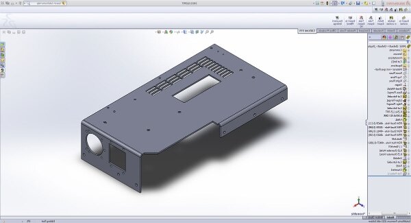
Wanneer een onderdeel is ontworpen in 3D CAD-software, is elke buiging, snede en tolerantie duidelijk gedefinieerd. Deze bestanden kunnen direct naar productiemachines worden gestuurd, zoals lasersnijders en kantpersen. Dit zorgt ervoor dat het afgewerkte onderdeel overeenkomt met het oorspronkelijke ontwerp. De naadloze overgang van digitaal bestand naar fysiek onderdeel elimineert onnodige stappen en versnelt de productie.
Voor hedendaagse productontwikkelingsteams verbetert 3D CAD-integratie ook het teamwerk. Ontwerpers kunnen modellen bijwerken, wijzigingen direct delen en controleren of het ontwerp klaar is voor productie voordat de productie begint. Dit voorkomt dure fouten, verkort de doorlooptijd en maakt het mogelijk om prototypes snel te testen en te verfijnen.
Waarom 3D CAD integratie belangrijk is bij plaatwerk prototyping?
Een sterke CAD-integratie zorgt ervoor dat elk ontwerpdetail consistent blijft van scherm tot werkplaats. Het verbetert de precisie, het teamwerk en de productie-efficiëntie terwijl kostbare fouten worden verminderd.
Handmatige gegevensconversie elimineren
Voordat CAD systemen direct met elkaar verbonden konden worden, moesten engineers vaak ontwerpbestanden converteren naar verschillende formaten voor elke machine die ze gebruikten. Elke conversie verhoogde het risico op verlies van afmetingen of geometrie, wat leidde tot kleine fouten tijdens de fabricage. Zelfs kleine afwijkingen konden leiden tot herbewerking of een compleet nieuw ontwerp.
Met breed ondersteunde formaten zoals STEP, IGES en DXF kunnen ontwerpgegevens rechtstreeks worden geïmporteerd in lasersnijden, buigenof CNC-systemen. De geometrie blijft nauwkeurig en kenmerken zoals gaten, bochten en uitsparingen blijven trouw aan het oorspronkelijke model. Deze directe gegevensstroom maakt handmatige correcties overbodig, bespaart insteltijd en vermindert de kans op menselijke fouten.
Samenwerking tussen ontwerpers en fabrikanten stroomlijnen
Bij prototypeontwikkeling is timing alles. 3D CAD-compatibiliteit vergemakkelijkt teamwerk doordat ontwerpers en constructeurs vanaf hetzelfde model kunnen werken. In plaats van 2D tekeningen of screenshots te sturen, kunnen ontwerpers een gedetailleerd 3D-bestand delen waarin elke functie is vastgelegd.
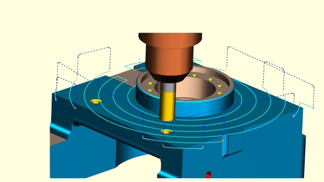
Fabrikanten kunnen het model openen, bekijken en ontwerpwijzigingen voorstellen op basis van echte productieomstandigheden. Ze kunnen ook simulaties uitvoeren om buiglimieten of materiaalgebruik te testen voordat de productie begint. Deze open communicatie helpt misverstanden voorkomen en zorgt ervoor dat de ontwerpintentie behouden blijft.
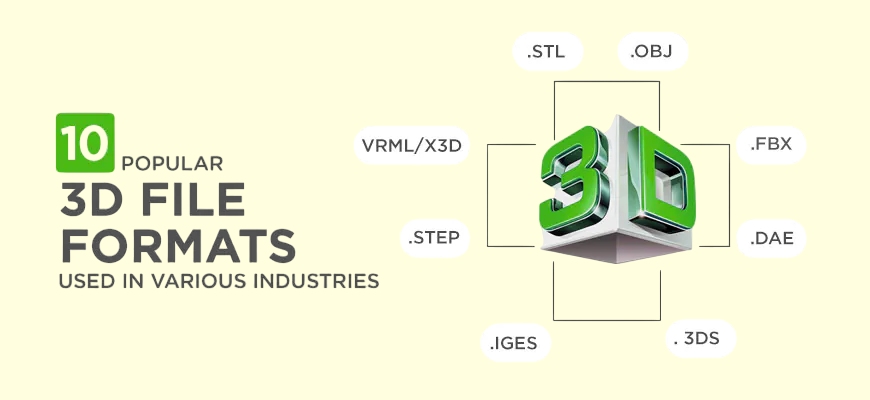
Standaard 3D CAD bestandsindelingen bij productie
Elk bestandsformaat dient een specifiek doel bij digitale fabricage. Weten wanneer je DXF, STEP of IGES moet gebruiken, zorgt voor een soepele gegevensoverdracht en voorkomt productievertragingen.
DXF (Drawing Exchange Format)
DXF-bestanden worden veel gebruikt bij het lasersnijden en CNC ponsen. Ze slaan 2D-geometrie op die de vlakke lay-out van een plaatmetalen onderdeel definieert. Aangezien de meeste lasersnijsoftware DXF-bestanden rechtstreeks leest, werkt dit formaat goed voor het uitlijnen, specificeren van gatposities en het maken van contourpaden.
Ingenieurs exporteren DXF-bestanden meestal nadat ze 3D-modellen hebben uitgevouwen tot platte patronen. Hierdoor kunnen constructeurs onderdelen precies uitsnijden voordat ze worden gebogen of gevormd. De eenvoudige structuur van DXF maakt het ideaal voor vlakke onderdelen of componenten die geen volledige 3D-details nodig hebben.
STEP (standaard voor de uitwisseling van productgegevens)
STEP-bestanden zijn de meest voorkomende indeling voor het delen van 3D-modellen tussen verschillende CAD-systemen. Ze houden alle 3D geometrie en solid data intact. In tegenstelling tot 2D-formaten leggen STEP-bestanden complexe details vast, zoals bochten, vullingen en gaten in samenstellingen. Ze werken naadloos met software zoals SolidWorks, Inventor en CATIA.
Fabrikanten gebruiken STEP-bestanden om vervormingen te simuleren, te controleren op interferenties en de intentie van het ontwerp te bevestigen voor de productie. Door hun nauwkeurigheid en brede compatibiliteit zijn ze de eerste keuze voor moderne prototypes van plaatwerk.
IGES (Initial Graphics Exchange Specification)
IGES-bestanden waren een van de eerste formaten die ontwikkeld werden voor de uitwisseling van 3D-gegevens. Ze kunnen wireframe en oppervlaktegeometrie opslaan, waardoor ze handig zijn voor modellen met gebogen of vrije oppervlakken.
Hoewel nieuwere formaten zoals STEP IGES grotendeels hebben vervangen, is IGES nog steeds nuttig in projecten met oudere CAD-systemen of oppervlakte-gebaseerde ontwerpen. Veel fabricageprogramma's kunnen IGES lezen, waardoor oudere modellen hergebruikt kunnen worden in de huidige workflows zonder dat er een nieuw ontwerp nodig is.
De uitdagingen van incompatibele CAD-bestanden
Als CAD-bestanden niet goed overeenkomen, vertraagt het hele productieproces. Incompatibiliteit leidt tot gegevensverlies, vertragingen en hogere kosten, wat de levering van prototypes kan beïnvloeden.
Gegevensverlies en geometriefouten
Een belangrijk probleem met incompatibele CAD-bestanden is het verlies van gegevens tijdens de conversie. Wanneer een ontwerp wordt overgezet tussen verschillende CAD-programma's, kunnen kleine kenmerken zoals gaten, vullingen of buiglijnen verschuiven of verdwijnen. Deze kleine veranderingen veroorzaken vaak grote problemen zodra de fabricage begint.
Een ontbrekende radius of een uitsparing die niet gecentreerd is, kan er bijvoorbeeld voor zorgen dat onderdelen niet meer in elkaar gezet kunnen worden of niet meer goed functioneren. Zelfs een fout van een paar millimeter kan ervoor zorgen dat het onderdeel defect raakt. Technici moeten dan extra uren besteden aan het nakijken en corrigeren van tekeningen, wat tijdverlies oplevert.
Verhoogde doorlooptijd en kosten
Elke keer dat een bestandsoverdracht mislukt, moet iemand deze repareren. Herwerken, hertekenen en het herhaaldelijk controleren van bestanden verlengen de tijdlijn. De productie kan worden stilgelegd terwijl er op gecorrigeerde gegevens wordt gewacht, wat tot onnodige vertragingen leidt en de workflow verstoort.
Deze problemen brengen ook verborgen kosten met zich mee. Er zijn meer engineeringuren nodig, de communicatie tussen teams wordt frequenter en er kunnen testruns nodig zijn om de nauwkeurigheid te controleren. Elke extra bestandsconversie vergroot de kans op fouten, wat kan leiden tot verspilling van materialen en afgedankte onderdelen.
Hoe digitale productie deze problemen oplost?
Digitale productie stroomlijnt de bestandsverwerking, waardoor deze soepeler en sneller verloopt. Het verbindt ontwerptools rechtstreeks met productiemachines, waardoor CAD-gegevens met weinig handmatige inspanning worden omgezet in productieklare instructies.
Slimme bestandsbeheersystemen
Moderne productiesoftware kan verschillende CAD formaten verwerken, waaronder STEP, IGES en DXF. Deze systemen lezen automatisch geometrie in, detecteren ontbrekende gegevens en signaleren problemen voordat de productie begint. Als er een gat, kromming of uitlijnprobleem optreedt, markeert het systeem dit onmiddellijk zodat technici het kunnen oplossen zonder materiaal of tijd te verspillen.
Briljante bestandsverwerking omvat ook automatische controles op machinecompatibiliteit. De software controleert de materiaaldikte, buigtoleranties en nauwkeurigheid van het vlakke patroon. Als alles door de inspectie komt, wordt het bestand voorbereid voor lasersnijden of buigen.
Geïntegreerde CAM-workflows
CAD-integratie stopt niet bij het delen van bestanden. Geavanceerde systemen koppelen CAD direct aan CAM software, die CNC machines, lasersnijders en afkantpersen aanstuurt. Zodra een 3D model klaar is, maakt het systeem automatisch de toolpaths en instructies die nodig zijn voor de productie.
CAM-software kan bijvoorbeeld direct vanuit het model snijpaden en buigvolgorden genereren, zodat handmatig coderen niet meer nodig is. Het kan ook onderdelen op een plaat rangschikken om uitval te minimaliseren en materiaal te besparen.
Shengen's 3D CAD-compatibele mogelijkheden voor prototyping
Bij Shengen verbindt onze digitale workflow ontwerp, engineering en productie in één soepel proces. Deze aanpak zorgt voor een snelle doorlooptijd, hoge precisie en consistente kwaliteit vanaf het uploaden van het bestand tot de uiteindelijke levering.
Accepteert alle belangrijke bestandsformaten
We ondersteunen alle standaard CAD-formaten, waaronder DXF, STEP, IGES en andere veelgebruikte technische formaten. Of u nu ontwerpt in SolidWorks, AutoCAD, Fusion 360 of CATIA, uw bestanden kunnen direct worden geüpload zonder detailverlies. Deze brede compatibiliteit maakt handmatige conversie overbodig, zodat we snel met de productie kunnen beginnen.
Ons team controleert elk bestand zorgvuldig tijdens het importeren om de nauwkeurigheid te garanderen. Alle kenmerken - gaten, bochten en uitsnijdingen - worden precies zo bewaard als ze zijn ontworpen. Zelfs complexe geometrieën met krappe toleranties kunnen nauwkeurig worden gereproduceerd. Dit proces bespaart tijd en zorgt ervoor dat elk ontwerp trouw blijft aan de oorspronkelijke bedoeling.
DFM-overzicht
Voordat de productie begint, voeren onze technici een DFM-beoordeling (Design for Manufacturability) uit om optimale maakbaarheid te garanderen. Deze stap zorgt ervoor dat het onderdeel efficiënt kan worden gemaakt en voldoet aan de fabricagelimieten in de praktijk. We controleren details zoals buigradii, afstand tussen gaten en materiaaldikte om er zeker van te zijn dat het ontwerp compatibel is met onze processen.
Als we potentiële problemen vinden, zoals krappe bochten of onvoldoende speling, geven we praktische suggesties om de maakbaarheid te verbeteren. Deze vroege beoordeling helpt herbewerking te voorkomen, verlaagt de kosten en zorgt ervoor dat elk prototype voldoet aan de prestatieverwachtingen.
Digitale precisie en snelle doorlooptijd
Onze CAD-, CAM- en productiesystemen zijn volledig met elkaar verbonden, dus zodra een ontwerp is goedgekeurd, worden de productie-instructies automatisch gegenereerd. Het lasersnijden, buigen en afwerken kan onmiddellijk beginnen, zonder vertraging.
Automatisering en geavanceerde nestsoftware helpen ons de insteltijd en materiaalverspilling te verminderen, terwijl de resultaten van topkwaliteit blijven. Elke stap gebruikt dezelfde geverifieerde CAD-gegevens, zodat snelheid nooit ten koste gaat van nauwkeurigheid.
Tips om uw 3D CAD bestand voor te bereiden voor prototyping
Een goed voorbereid CAD-bestand zorgt voor een soepele productie en voorkomt nabewerking. Als je een paar eenvoudige stappen volgt, is je ontwerp klaar om snel en nauwkeurig prototypes te maken.
Vereenvoudig je model
Richt je op de belangrijkste functionele kenmerken van je onderdeel. Verwijder kleine cosmetische details zoals logo's, vullingen of decoratieve lijnen die de prestaties niet beïnvloeden. Deze extra's kunnen het bewerken of lasersnijden vertragen en onnodige complexiteit toevoegen.
Controleer uw model op verborgen lichamen, overlappende oppervlakken of ongebruikte schetsen. Vereenvoudigde geometrie maakt het eenvoudiger voor ingenieurs om onderdelen zonder fouten uit te vouwen, te programmeren en te fabriceren. Een schoon, lichtgewicht model zorgt voor snellere verwerking en een nauwkeuriger begrip van uw ontwerpintentie.
Duidelijke opmerkingen en toleranties opnemen
Voeg alle essentiële productiedetails direct toe aan je CAD-model of bijgevoegde tekening. Geef duidelijk materiaalsoort, plaatdikte en oppervlakteafwerking op. Als je onderdeel nauwe toleranties vereist, noteer ze dan en zorg ervoor dat ze haalbaar zijn voor het geselecteerde fabricageproces.
Je kunt bijvoorbeeld ±0,1 mm voor gatdiameters of ±1° voor bochten definiëren. Het verstrekken van deze details helpt engineers bij het kiezen van de juiste gereedschappen en opstellingen. Het voorkomt ook verwarring tijdens het offreren en zorgt ervoor dat het prototype voldoet aan uw ontwerpverwachtingen.
Exporteren in neutrale indelingen
Wanneer je je bestand opslaat, gebruik dan neutrale formaten zoals STEP (.stp) of IGES (.igs) om het delen tussen verschillende CAD- en CAM-systemen te vergemakkelijken. Deze formaten bewaren de geometrie nauwkeurig en zijn standaard in de productie.
Als uw onderdeel 2D lasersnijden vereist, voeg dan een DXF (.dxf) bestand bij met de vlakke lay-out. Controleer altijd de exportinstellingen om te controleren of alle lagen, eenheden en kenmerken zijn opgenomen. Door nauwkeurige en volledige CAD-gegevens mee te sturen, helpt u uw fabrikant om snel en efficiënt nauwkeurige prototypes te maken.
Wat gebeurt er als je geen CAD-bestand hebt?
Niet elk project begint met een kant-en-klaar 3D-model. Veel klanten komen naar ons met alleen een schets, een foto of een bestaand voorbeeldonderdeel. Dat is helemaal prima. Voor moderne prototypes hoef je geen CAD-software te beheersen - alles wat je nodig hebt is een duidelijk idee en een paar belangrijke metingen.
Van idee tot 3D-model
Als je geen CAD-bestand hebt, kun je nog steeds beginnen met het aanleveren van schetsen, foto's of eenvoudige tekeningen. Zelfs een handgetekende schets met de belangrijkste afmetingen is genoeg voor ingenieurs om te begrijpen wat je ontwerp inhoudt. Het delen van details zoals materiaal, functie en werkomgeving helpt ons team ook bij het ontwerpen van een nauwkeurig en produceerbaar model.
Of je project nu een mechanische beugel, een behuizing of een decoratief paneel is, onze ingenieurs kunnen het digitaal namaken met professionele CAD-tools. Het uiteindelijke model heeft een nauwkeurige geometrie en is klaar voor fabricage.
Teken- en ontwerpassistentie van Shengen
Bij Shengen helpt ons engineeringteam je concept om te zetten in een productieklaar ontwerp. Als je alleen een schets of voorbeeldonderdeel hebt, kunnen we een gedetailleerd 2D of 3D CAD-bestand maken op basis van jouw input.
We beginnen met een kort consult om uw vereisten te bevestigen, inclusief afmetingen, materiaal, dikte en prestatiebehoeften. Onze ingenieurs bouwen dan een produceerbaar model en controleren elke functie om een probleemloze fabricage en montage te garanderen. Je ontvangt een digitaal voorbeeld ter controle en goedkeuring voordat we met de productie beginnen.
Upload vandaag nog uw 3D CAD-bestand voor een directe offerte en DFM beoordeling. Het digitale productieplatform van Shengen transformeert uw ontwerp van concept tot afgewerkt metalen onderdeel - en dat alles binnen enkele dagen.
FAQs
Welke bestandsindelingen ondersteunt Shengen?
Shengen accepteert alle belangrijke 3D en 2D bestandsformaten, inclusief STEP (.stp), IGES (.igs), DXF (.dxf) en SolidWorks bestanden. Deze formaten werken naadloos samen met onze digitale fabricagesystemen, waardoor een nauwkeurige gegevensoverdracht van ontwerp naar productie wordt gegarandeerd zonder dat handmatige conversie nodig is.
Hoe kan ik ervoor zorgen dat mijn CAD-bestand klaar is voor productie?
Controleer voor het uploaden of je bestand alle belangrijke details bevat, zoals materiaalsoort, plaatdikte en oppervlakteafwerking. Verwijder alle onnodige geometrie, zoals decoratieve vullingen, ongebruikte lagen of kleine cosmetische kenmerken. Exporteer uw uiteindelijke model in een neutraal formaat, zoals STEP of IGES, om nauwkeurige afmetingen te behouden en ontbrekende elementen te voorkomen.
Kunnen er ontwerpwijzigingen worden aangebracht nadat ik mijn CAD-bestand heb ingediend?
Ja. Als je je ontwerp moet aanpassen, upload dan het herziene CAD-bestand. Onze technici zullen de update bekijken, de maakbaarheid opnieuw controleren en de wijzigingen bevestigen voordat we overgaan tot productie.
Hoe lang duurt het voordat ik een prototype ontvang?
De doorlooptijd is afhankelijk van de complexiteit van het onderdeel, de materiaalkeuze en de afwerkingsvereisten. In de meeste gevallen kunnen we prototypes binnen een paar dagen produceren en verzenden.
Hey, ik ben Kevin Lee

De afgelopen 10 jaar heb ik me verdiept in verschillende vormen van plaatbewerking en ik deel hier de coole inzichten die ik heb opgedaan in verschillende werkplaatsen.
Neem contact op
Kevin Lee
Ik heb meer dan tien jaar professionele ervaring in plaatbewerking, gespecialiseerd in lasersnijden, buigen, lassen en oppervlaktebehandelingstechnieken. Als technisch directeur bij Shengen zet ik me in om complexe productie-uitdagingen op te lossen en innovatie en kwaliteit in elk project te stimuleren.
Verwante bron

Vingerafdrukbestendig roestvrij staal: hoe het werkt en hoe te kiezen

OEM vs Loonproductie: Hoe het juiste model voor uw project te kiezen

Setupkosten vs eenheidskosten bij de productie van plaatmetaal
