Il controllo qualità non è una fase di ispezione finale: è il meccanismo che decide se i pezzi di lamiera funzionano correttamente sul campo. Un pezzo può superare le misure di base, ma deformarsi sotto carico, perdere l'adesione del rivestimento dopo tre mesi o causare un disallineamento dell'intero assemblaggio. Nella produzione reale, i guasti raramente si verificano al momento della spedizione; in genere hanno origine a monte.
La fabbricazione di lamiere comprende una serie di processi, tra cui taglio, piegatura, saldatura, formatura e finitura. Ogni fase comporta dei rischi. I dati provenienti dagli impianti di fabbricazione indicano che affrontare i difetti in anticipo è economicamente vantaggioso, ma correggerli dopo il completamento può essere 10-20 volte più costoso. La prevenzione costa sempre meno della riparazione.
Le fondamenta di qualsiasi programma di controllo qualità sono la verifica dei materiali e il controllo integrato dei processi. Quando la qualità delle materie prime è stabile e ogni fase di produzione ha dei punti di controllo, la qualità diventa ripetibile, anziché accidentale.
Quadro di riferimento per il controllo qualità nella lavorazione della lamiera
Un sistema di controllo qualità deve iniziare prima che inizi la fabbricazione. La variazione del materiale influisce direttamente su formabilità, ritorno elastico, penetrazione della saldatura, comportamento alla corrosione e durata a fatica.
Verifica dei materiali e qualificazione dei fornitori
La consistenza del materiale è la prima barriera contro i difetti. Il carico di snervamento, lo spessore, la durezza e l'allungamento devono corrispondere ai requisiti tecnici, non alle approssimazioni.
Parametri di tolleranza tipici dei materiali:
| Parametro | Tolleranza generale | Tolleranza di precisione |
|---|---|---|
| Spessore della lastra | ±0,05-0,10 mm | ≤±0,03 mm |
| Deviazione della forza | <5% da specifiche | <3% deviazione |
| Stato della finitura superficiale | Segni minori accettabili | Nessun difetto nelle aree visibili |
Un fornitore che mantiene una variazione della bobina di ±0,02 mm in tre lotti consecutivi riduce il carico di lavoro delle ispezioni in entrata di 40-60%. La sola certificazione non è sufficiente: i pezzi critici spesso richiedono campionamenti di durezza o controlli di trazione per verificare l'effettivo comportamento meccanico.
Esempio di caso di fallimento
Un lotto di acciaio inossidabile superava i controlli visivi ma aveva un contenuto di zolfo di 0,03% superiore alla tolleranza. Sei mesi dopo, i punti di saldatura si sono incrinati durante i cicli di lavaggio. Se fosse stata inclusa la verifica metallurgica, il fallimento sarebbe stato evitato.
Controllo qualità integrato nel processo durante la produzione
La qualità si crea in fase di produzione, non alla fine. L'ispezione del primo articolo convalida l'angolo di piegatura, l'accuratezza del taglio e il ritorno elastico prima che inizi la produzione completa. Una tolleranza di piegatura di ±1° può sembrare piccola, ma può spostare i modelli di fori di 1,5 mm in un involucro multiforme.
Punti di controllo del CQ di produzione raccomandati:
| Palcoscenico | Metriche critiche | Rischio se non controllato |
|---|---|---|
| Taglio | Larghezza del cordolo, bava, direzione della grana | Fallimento dell'accoppiamento + aumento dell'usura degli utensili |
| Piegatura | Angolo, ritorno elastico, raggio | Disallineamento porta/cerniera |
| Saldatura | Apporto di calore, uniformità del cordone | Deformazione del telaio + fessurazione a lungo termine |
| Finitura | Spessore del rivestimento 60-90 µm | Ruggine o scrostatura |
Un sistema di hold-point, in cui la produzione si ferma fino all'approvazione del controllo qualità, riduce in genere gli scarti di 30-50% entro 1-3 cicli di produzione. La qualità controllata in anticipo diventa qualità protetta in seguito.
Metodi di ispezione, valutazione delle saldature e test delle prestazioni del rivestimento
Anche con un buon controllo dei materiali e dei processi, la qualità non significa nulla finché non viene misurata. L'ispezione non è uno strumento unico, ma un sistema stratificato che convalida la geometria, l'integrità della saldatura, la durata del rivestimento e le condizioni della superficie. Un risultato affidabile richiede tutti e quattro gli strumenti.
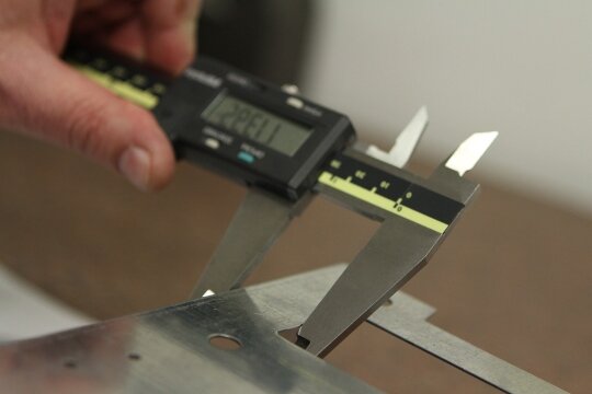
Misurazione dimensionale e verifica delle tolleranze
La precisione dimensionale determina il successo dell'assemblaggio. La maggior parte dei guasti del software non è causata da un singolo errore significativo, ma piuttosto da diversi piccoli errori che si accumulano.
Strumenti di misura tipici
- Calibri a corsoio, micrometri, calibri a perno
- Misuratori di altezza per offset e livelli a gradini
- CMM o scansione laser per geometrie complesse (±0,02-0,05 mm ottenibili)
I difetti dimensionali aumentano rapidamente. Una deviazione dell'angolo di piega di 1,2° su più pieghe può provocare uno spostamento di oltre 2 mm nel foro di montaggio, sufficiente a causare il bloccaggio della cerniera o la vibrazione del pannello.
Riferimenti di tolleranza raccomandati
| Caratteristica | Obiettivo standard | Obiettivo di alta precisione |
|---|---|---|
| Spaziatura tra i fori | ±0,10-0,15 mm | ≤±0,08 mm |
| Planarità (luce 300-600 mm) | ≤0,3-0,5 mm | ≤0,25 mm |
| Angolo di curvatura | ±1° | ±0,5° o inferiore |
Se gli angoli passano ma la planarità fallisce → la causa è spesso il ritorno elastico + la direzione della grana.
Se la spaziatura passa ma l'adattamento fallisce → la tolleranza cumulativa + l'allineamento devono essere ricontrollati a livello di assemblaggio.
Condizioni della superficie e ispezione della qualità visiva
Un pezzo può essere dimensionalmente corretto ma non essere accettato a causa di difetti superficiali. I criteri estetici sono più importanti per gli involucri, i pannelli delle porte, le coperture e i componenti visibili al cliente.
Parametri di riferimento per la finitura superficiale
- Vernice a polvere: Ra 1,6-3,2 μm
- Inox spazzolato: Ra 0,4-0,8 μm
- Pannelli decorativi lucidati a specchio: Ra ≤0,2 μm
L'ispezione deve avvenire con un'illuminazione diffusa di 500-1000 lux per aumentare la visibilità dei difetti di ~30%.
| Difetto | Causa principale | Prevenzione |
|---|---|---|
| Ondulazione | Usura di utensili e stampi | Sostituire le matrici nei tempi previsti |
| Microdent | Danno da movimentazione | Utilizzare ganasce morbide + pellicola protettiva |
| Fori del rivestimento | Contaminazione da olio | Migliorare il pretrattamento |
Il controllo qualità delle superfici non è estetico: controlla la resistenza alla corrosione, le prestazioni di tenuta e la percezione del cliente.
Integrità delle saldature e verifica dei giunti
Le saldature determinano la sopravvivenza strutturale.
Una saldatura possono apparire lisci, eppure si guastano in servizio, soprattutto se sottoposti a vibrazioni nell'intervallo 20-80 Hz nel corso del tempo.
Approccio di ispezione della saldatura a più livelli
1) Accettazione visiva della saldatura
- Nessun cluster di porosità
- Sottotaglio ≤10% della dimensione del filetto
- Perlina uniforme con dita pulite
- Nessuna crepa da cratere o eccessiva colorazione da calore
2) Metodi NDT per giunti ad alta resistenza
| Metodo | Rileva | Adatto per |
|---|---|---|
| Colorante Penetrante (PT) | Crepe superficiali | Inox → alluminio |
| Particella magnetica (MT) | Fessure sottosuperficiali | Acciai ferrosi |
| Ultrasuoni (UT) | Vuoti interni | Telai ad alto carico |
La scansione a ultrasuoni a 2-5 MHz rileva la mancanza di fusione prima che si propaghino le cricche, prevenendo i guasti sul campo.
3) Convalida meccanica
Le saldature di raccordo corrette raggiungono 70-100% della resistenza del metallo di base.
Se le saldature risultano inferiori a 60% → l'apporto termico, il tipo di riempimento o il montaggio devono essere corretti immediatamente.
Schema di guasto comune:
Troppo caldo → distorsione/warping
Troppo freddo → microfrattura fragile + perdita di fusione
Test di spessore, adesione e corrosione del rivestimento
Finitura non è solo una decorazione: è uno strato di durata. La verniciatura a polvere a 60-90 μm garantisce una protezione dalla corrosione senza crepe.
Riferimenti per i test di prestazione
- Test di adesione trasversale: Spaziatura della griglia di 1 mm
- Nebbia salina: <240 ore → uso interno
- 480-1000 ore → grado industriale/esterno
- Test di adesione trasversale: Spaziatura della griglia di 1 mm
Se l'adesione fallisce, la causa è tipicamente il pretrattamento e non il rivestimento.
Documentazione, tracciabilità e controllo statistico
L'ispezione non significa nulla senza la ripetibilità. Una fabbrica diventa coerente quando il controllo qualità non dipende dai singoli operatori.
I flussi di lavoro guidati da ISO definiscono
- Come vengono effettuate le misurazioni
- Quando si attiva l'azione correttiva
- Quali dati devono rimanere tracciabili
Il monitoraggio delle tendenze SPC previene i guasti prima che si verifichino. Se il Cpk di piegatura è < 1,33, il processo non è statisticamente stabile → è necessario regolare l'usura dello stampo o la compensazione dell'angolo.
La tracciabilità consente di individuare le cause principali: Se la corrosione compare dopo sei mesi, il controllo qualità deve conoscere il lotto della bobina, l'operatore, il turno, il bagno di pretrattamento e la curva di cottura.
Le fabbriche ad alte prestazioni non vedono il fallimento, anzi lo prevedono.
Controllo qualità (CQ) a livello di assemblaggio
L'ispezione non termina quando un singolo pezzo supera la misurazione. L'accuratezza assoluta è confermata solo quando i componenti sono assemblati e funzionano come un tutt'uno. L'impilamento delle tolleranze, il ritiro delle saldature e il ritorno elastico possono trasformare un pezzo "corretto" in un assemblaggio fallito.
Piccole deviazioni aggravano la situazione. Un pannello con un angolo di curvatura di soli 0,3° può comportare un disallineamento delle cerniere di 1,6-2,2 mm dopo quattro pieghe, sufficiente a causare il trascinamento della porta, vibrazioni o interferenze durante il funzionamento della macchina.
Verifica dell'assemblaggio
L'obiettivo è convalidare il parallelismo, la torsione, la planarità e l'allineamento dei fori sotto la pressione dell'assemblaggio reale, non solo su un disegno.
Parametri di riferimento del CQ di assemblaggio
| Punto di controllo | Obiettivo consigliato |
|---|---|
| Differenza diagonale del telaio | ≤0,5-1,0 mm |
| Parallelismo ferroviario | ≤0,10-0,20 mm per 500 mm |
| Spazio tra porta e cerniera | Entro ±0,5 mm |
| Ritenzione del precarico del dispositivo di fissaggio | ≤10-15% caduta di coppia |
Se la planarità è corretta singolarmente, ma la torsione compare dopo l'avvitamento, il problema non risiede nella lavorazione, ma nelle tensioni residue e nel serraggio non uniforme.
Test di carico e vibrazioni funzionali
La geometria mostra la forma del pezzo. La prova di carico determina se un sistema è in grado di resistere alle sollecitazioni del mondo reale.
Linee guida tipiche per la validazione
| Tipo di componente | Requisiti di prestazione |
|---|---|
| Telaio della macchina | <1,5 mm di deflessione a carico nominale |
| Pannelli in lamiera strutturale | 1,25-1,50× fattore di prova del carico |
| Cerniere / coperture di accesso | Resistenza a 50.000-100.000 cicli |
| Strutture saldate | Testato con vibrazioni di 20-80 Hz |
Se un pannello supera il controllo qualità dimensionale ma risuona a 60-80 Hz, le microfessure possono comparire in settimane, non in anni. Il controllo qualità dell'assemblaggio conferma non solo l'adattamento, ma anche la sopravvivenza in condizioni di lavoro.
Convalida dell'affidabilità a lungo termine e comportamento a fatica
L'ispezione a breve termine rileva la geometria. La convalida a lungo termine assicura che il prodotto rimanga stabile in condizioni reali. È qui che molti produttori si fermano, e dove iniziano i guasti veri e propri.
Simulazione ambientale e dell'invecchiamento
I prodotti in lamiera sono sensibili alla corrosione, all'espansione termica, alla rottura dei raggi UV e alle sollecitazioni cicliche. Questi aspetti devono essere testati prima della consegna, non devono essere scoperti sul campo.
Test di affidabilità accelerati
- Nebbia salina 240-1000 ore, a seconda del grado ambientale
- Cicli termici 10°C ↔ 70°C (multirotondo)
- Esposizione ai raggi UV per gruppi verniciati a polvere per esterni
- Test di resistenza alle vibrazioni per la crescita della fatica
Quando l'adesione del rivestimento si degrada durante i test di invecchiamento, lo scorrimento dei bordi e la corrosione sotto il film sono inevitabili.
Fatica, rilassamento da sforzo e deformazione residua
Alcune modalità di guasto sono invisibili al momento della spedizione, ma fatali dopo l'uso.
Indicatori di rischio di affaticamento
- Cricche in corrispondenza dei punti di saldatura o dei raggi di curvatura stretti
- Instabilità della lastra in prossimità di punti di carico ad alta sollecitazione
- Allentamento degli elementi di fissaggio dopo il ciclo termico
Tecniche di prevenzione
| Modalità di guasto | Misura preventiva |
|---|---|
| Fatica di saldatura | Lisciatura delle dita dei piedi / controllo del calore / soffietto |
| Crescita della cricca di flessione | Aumento del raggio di curvatura + controllo della direzione della grana |
| Perdita di precarico del bullone | Bloccaggio della filettatura + programmazione della verifica della coppia |
Un bullone serrato a 25 Nm può scendere a 15 Nm dopo un ciclo termico, creando un movimento anche se il giunto "sembra a posto".
Progettazione per l'ispezione e intelligenza predittiva della qualità
La migliore affidabilità non deriva da un numero maggiore di ispezioni, ma da design facile da ispezionare.
Strategie DFI che riducono i tempi del CQ del 50-70%:
- Aggiungere schede di riferimento e superfici di tastatura
- Mantenere accessibili i percorsi di scansione della saldatura
- Fornire patch di prova del rivestimento in prossimità dei bordi
- Evitare possibilmente giunti interni nascosti
Se a questo si aggiunge il controllo qualità digitale, che comprende SPC, monitoraggio delle tendenze CPK e rilevamento automatico delle visioni, il sistema inizia a prevedere le deviazioni prima dei guasti. Le fabbriche ad alta maturità non rilevano i problemi. Li prevedono.
Miglioramento continuo della qualità e controllo scalabile della produzione
La qualità non è un punto di controllo, ma un sistema. Le fabbriche che si limitano a ispezionare i pezzi reagiscono ai problemi. Le fabbriche che imparano dai dati di ispezione prevengono i problemi.
Analisi delle cause e azioni correttive
I difetti ripetuti non sono errori di ispezione, ma indicatori di instabilità del processo. Se la deviazione della piega aumenta dopo 5.000 cicli, il problema è probabilmente dovuto all'usura dell'utensile, piuttosto che a un errore dell'operatore. Un numero maggiore di ispezioni non risolverà la deriva, ma l'azione correttiva sì.
Fasi di RCA efficaci
| Palcoscenico | Obiettivo |
|---|---|
| Identificare i difetti ricorrenti | Osservare il modello, non il sintomo |
| Determinare il driver del guasto | Utensili / materiale / operatore / controllo del calore |
| Attuare l'azione correttiva | Modifica del processo > rilavorazione manuale |
| Convalidare il recupero | I dati devono confermare il miglioramento |
Feedback a ciclo chiuso: CQ → Progettazione → Produzione
La qualità diminuisce quando le informazioni fluiscono all'indietro. L'ispezione dimensionale regola la compensazione della piegatura. Il feedback sulla distorsione della saldatura migliora la strategia di fissaggio. I guasti dovuti alla nebbia salina inducono a rivedere la chimica di pretrattamento. Questo ciclo garantisce che ogni successivo ciclo di produzione sia più stabile del precedente.
Le fabbriche che eseguono il controllo qualità a ciclo chiuso riducono in genere gli scarti 20-50% entro 3-6 mesi, anche senza nuovi macchinari, solo grazie a un migliore utilizzo dei dati.
Costi, rilavorazioni e stabilità delle consegne: il vero ROI della qualità
La qualità non riduce solo i difetti, ma anche le perdite di capacità, di tempo e di clienti.
La rilavorazione dei pannelli dopo il rivestimento può costare 10-20 volte di più rispetto alla correzione di un angolo di piegatura durante la validazione del primo pezzo. Quando i difetti sopravvivono all'assemblaggio finale, le date di consegna slittano e la fiducia raramente si recupera.
CQ scalabile = Capacità di produzione scalabile
Una fabbrica diventa scalabile quando la sua produzione è prevedibile. Un controllo qualità standardizzato garantisce la ripetibilità tra turni, lotti e operatori. La tracciabilità accelera le indagini anziché le congetture. Il monitoraggio predittivo impedisce ai guasti di uscire dall'edificio.
Conclusione
La verifica dei materiali previene i difetti nei punti di controllo dell'origine e del processo per bloccare le variazioni prima che si moltiplichino. L'ispezione dimensionale dimostra la geometria. Il miglioramento continuo rende prevedibili i risultati. I pezzi buoni non sono fortuna. I pezzi buoni sono progettati, verificati, testati e continuamente migliorati.
Se state ottimizzando il vostro flusso di lavoro del CQ, riducendo le rilavorazioni o migliorando la coerenza delle saldature, possiamo aiutarvi. Inviate i vostri disegni, i requisiti di tolleranza o i problemi di qualità a: sales@goodsheetmetal.com
Rispondiamo con raccomandazioni di controllo qualità attuabili, feedback sulla producibilità e percorsi di miglioramento su misura per la vostra realtà produttiva.
Domande frequenti
Qual è la tolleranza accettabile nella lavorazione della lamiera?
±0,10-0,15 mm è lo standard per la distanza tra i fori, ±1° per le curve. Le custodie di precisione possono richiedere una tolleranza di ≤±0,08 mm e una tolleranza angolare di ±0,5°.
Come si verifica la qualità della saldatura nella fabbricazione dei metalli?
Le saldature vengono valutate mediante ispezione visiva, colorante penetrante (PT), particelle magnetiche (MT), test a ultrasuoni (UT) e test di taglio meccanico.
Cosa causa il disallineamento dell'assemblaggio anche quando le parti sono misurate correttamente?
L'impilamento delle tolleranze, il ritorno elastico, la distorsione da ritiro della saldatura e l'errore di riferimento sono i fattori principali.
Qual è lo spessore della verniciatura a polvere sulle parti metalliche?
La maggior parte delle applicazioni industriali richiede uno spessore del rivestimento di 60-90 μm. <Uno spessore inferiore a 60 μm aumenta il rischio di corrosione; uno spessore superiore a 100 μm aumenta il rischio di scheggiatura.
Come si previene la cricca da fatica nelle strutture in lamiera?
Controllare l'apporto di calore della saldatura, aumentare i raggi di curvatura, allineare la direzione della grana, lisciare i cordoni di saldatura e convalidare in presenza di vibrazioni a frequenze comprese tra 20 e 80 Hz.
Ciao, sono Kevin Lee

Negli ultimi 10 anni mi sono immerso in varie forme di lavorazione della lamiera, condividendo qui le mie esperienze in diverse officine.
Contattate
Kevin Lee
Ho oltre dieci anni di esperienza professionale nella fabbricazione di lamiere, con specializzazione nel taglio laser, nella piegatura, nella saldatura e nelle tecniche di trattamento delle superfici. In qualità di direttore tecnico di Shengen, mi impegno a risolvere sfide produttive complesse e a promuovere innovazione e qualità in ogni progetto.
Risorsa correlata

Acciaio elettrozincato: guida alla lavorazione e alla scelta

Punzonatura e taglio laser: Costi, velocità e compromessi DFM

Lavorazione del filetto: Cosa determina il costo e la qualità dei pezzi
