Designers often face problems when parts don’t fit or function as planned. This usually happens because of confusion between two key concepts—tolerance and allowance. Engineers, machinists, and buyers must know how these terms affect the outcome of a product. Even the most advanced manufacturing process can lead to rework or failure without clear guidelines.
Tolerance is the range of acceptable variation in a part’s dimension. Allowance is a planned difference between two mating parts. Tolerance controls what’s allowed. Allowance sets the gap or fit between parts. Knowing both helps teams decide how loose or tight a part should be. This ensures smooth function, good assembly, and minimal waste.
These two terms sound similar. However, their roles in design and manufacturing are very different. Let’s break them down.
Tolerance in Design: The Basics You Need to Know
Every part you design has a size. But in real production, that size can’t be perfect every time. That’s where tolerance comes in.
What Is Tolerance in Engineering?
Tolerance means the allowed range a dimension can vary from its stated size. It’s a way to say, “This part doesn’t have to be exact, but it needs to stay within these limits.” Without tolerance, every part would need to be perfect. That’s not realistic.
For example, if a hole is marked as 10 mm ± 0.1 mm, it can be between 9.9 mm and 10.1 mm. That small range makes it possible to mass-produce parts with confidence.
Types of Tolerances: Unilateral, Bilateral, and Limit
Tolerances can be shown in a few ways, each suited to different design needs:
- Unilateral Tolerance allows variation in one direction. For example, 10 mm +0.2 / -0.0 means the part can only be larger, not smaller.
- Bilateral Tolerance allows variation in both directions. A common form is ±0.1 mm, where a 10 mm part can be 9.9 mm to 10.1 mm.
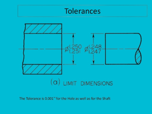
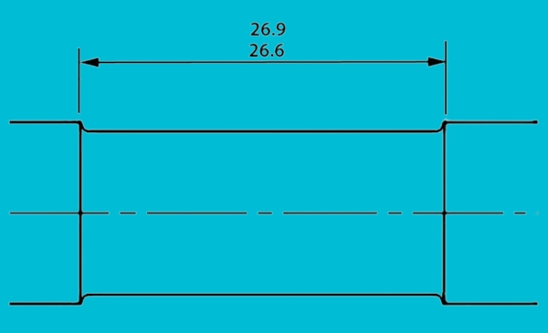
- Limit Tolerance gives the upper and lower limits directly. Instead of 10 mm ±0.1 mm, you say 9.9 mm to 10.1 mm.
Geometric Dimensioning and Tolerancing (GD&T) Basics
GD&T adds another layer to tolerance. It doesn’t just control size—it controls shape, orientation, and position. This is useful when parts need to fit or move in particular ways.
Symbols are used to show things like flatness, parallelism, or concentricity. For example, a cylinder might need to stay straight within 0.02 mm over its length.
Allowance in Engineering: Setting the Right Fit from the Start
Allowance controls the planned difference between two mating parts. It decides how tightly or loosely parts will go together.
What Is Allowance in Engineering Terms?
Allowance is the intentional gap or overlap between parts before they are assembled. Unlike tolerance, which allows for variation, allowance is a fixed design decision. It sets the minimum clearance or maximum interference.
If a shaft is 10 mm and the hole is 10.1 mm, the allowance is 0.1 mm. If the hole is 9.9 mm, the allowance is 0.1 mm of interference. This controls how parts fit—whether they slide, hold tight, or press in.
Allowance in Hole and Shaft Systems
In most designs, one part stays constant and the other changes. This is the idea behind the Hole Basis and Shaft Basis systems.
- Hole Basis System: The hole stays the same size. The shaft is adjusted to control the fit. This system is more common because standard tools and drills make fixed-size holes.
- Shaft Basis System: The shaft size stays the same. The hole changes to get the needed fit. Less common but useful in specific cases.
Types of Fits: Clearance, Transition, and Interference
Fits control how easily parts go together. There are three main types:
- Clearance Fit: The shaft is always smaller than the hole. Parts slide or rotate easily.
- Transition Fit: The shaft and hole are very close in size. Parts may slide or need light pressure to assemble, depending on the actual values.
- Interference Fit: The shaft is larger than the hole. The parts must be pressed together. This makes a strong, tight joint.
Fixed vs. Floating Fastener Conditions
In assemblies, fasteners go through holes. If both holes are fixed in position, it’s a fixed fastener condition. If one hole can move or shift, it’s a floating fastener condition.
Fixed conditions need tighter alignment tolerances. Floating conditions give more room to adjust during assembly.
Tolerance vs. Allowance: Clear Differences You Should Know
Both affect how parts fit. However, tolerance and allowance are not the same. Each serves a different role in design and production.
Conceptual Differences
Tolerance is about variation. It sets the acceptable range for a part to deviate from its ideal size.
Allowance is about intent. It defines the planned difference between mating parts, even before variation happens.
In short, tolerance is flexible, allowance is fixed.
Functional Differences in Assembly
Allowance decides the type of fit: loose, tight, or press. It tells you how the two parts will behave when joined.
Tolerance makes sure the final parts fall within limits. It ensures the design fit works, even when parts are made with slight differences.
Allowance serves a purpose. Tolerance makes sure that the objective is achieved.
Impact on Manufacturing and Inspection
Tighter tolerances mean more precision. That raises the cost and inspection time.
Allowance affects how parts are designed to fit. It influences decisions like press-fit vs. slip-fit or how much force is needed to assemble.
During inspection, tolerance is measured and verified. Allowance is reviewed at the design stage.
Examples from Real-World Applications
Slip-fit gears need a small clearance allowance. Tolerances ensure they slide but don’t wobble.
Press-fit bearings need an interference allowance. Tolerances keep the parts from being too loose or too tight.
Laptop hinges use transition fits. Allowance creates smooth movement. Tolerance ensures it stays that way over time.
| Aspect | Tolerance | Allowance |
|---|---|---|
| Concept | Acceptable variation in part size | Intentional difference between mating parts |
| Purpose | Controls manufacturing accuracy | Ensures proper fit between parts |
| Applies To | Individual part features | Relationship between two parts |
| When Defined | During part dimensioning | During fit design (e.g., shaft and hole) |
| Effect on Assembly | Ensures parts stay within functional limits | Determines if parts slide, press-fit, or hold |
| Effect on Cost | Tighter tolerance = higher cost | Allowance mainly affects function, not cost |
| Inspection | Verified with measurement tools | Reviewed at the design stage |
| Example | 10mm ±0.1mm hole (range 9.9–10.1mm) | 0.1mm clearance between 10mm shaft and 10.1mm hole |
How Tolerance Affects Manufacturing Decisions and Costs?
Every tolerance choice directly affects how parts are made, measured, and assembled.
Influence on Machining Processes
Loose tolerances are easier to machine. Most standard tools can hit the target without much setup.
Tight tolerances need special tools, slower speeds, and more precise control. That means more time and higher costs.
Holding a ±0.01 mm tolerance for CNC machining is much harder than ±0.1 mm. It can require custom fixturing or extra steps.
How Tight Tolerances Increase Costs?
Tighter tolerances mean:
- More tool wear
- More scrap
- More time for setup and measurement
- Higher inspection requirements
Each of these adds labor or delays. That’s why designers should use tight tolerances only when function demands it.
Tolerance Stack-Up in Assembly Design
Each part in an assembly has its tolerance. When you add them together, they can affect the final fit or motion. This is called tolerance stack-up.
If not controlled, it can cause parts to misalign or jam. Stack-up is a hidden risk in large assemblies. Designers must plan for it early.
Use of Tolerance Analysis Software
Modern CAD tools can simulate how tolerances affect an assembly.
Software like CETOL, SolidWorks TolAnalyst, or Sigmetrix can show:
- Worst-case fits
- Statistical outcomes
- Areas of risk
How does Allowance Guide Real-World Mechanical Design Choices?
Allowance significantly affects how parts move, hold, or wear. A reasonable allowance can distinguish between a smooth assembly and a failed part.
Designing for Mating Parts
When two parts fit together, allowance decides how they interact. It tells you if they will slide freely, lock tightly, or need force to join.
Engineers use allowances to plan the exact fit for shafts, holes, pins, and fasteners. This helps avoid loose joints or complex assemblies.
How does Allowance Affect Wear, Load, and play?
Clearance fits reduce friction. But too much clearance can cause vibration, noise, or early wear.
Interference fits hold tight, even under load. However, they can lead to stress buildup or damage during assembly if not designed carefully.
Case Studies: Shafts, Bearings, and Bushings
- Shafts and Bearings: A small clearance allowance is needed for smooth rotation without wobble.
- Bushings: Often use interference fits so they stay in place under force or rotation.
- Gear Assemblies: Use transition fits for accurate motion with minimal backlash.
Each case needs its allowance plan to work as intended.
Allowance in 3D Printing and CNC Machining
In 3D printing, allowance must account for material shrinkage and printer accuracy. Common practice is to leave 0.2–0.5 mm clearance between parts.
In CNC machining, allowance is easier to control. However, thermal expansion, tool deflection, or finish passes still affect final sizes. Good planning ensures parts fit without extra rework.
Why Adding Tolerance and Allowance Improves Your Design?
Good design isn’t just about shapes or functions. It also ensures parts can be made, assembled, and used without issues.
Prevents Assembly Issues
Apparent tolerance and allowance values ensure that parts fit together as they should. No guesswork. No forcing parts in place. That means fewer assembly delays and a lower risk of failure.
Improves Product Performance
A well-planned allowance can reduce play, increase stability, or ensure a smooth slide. Correct tolerances keep the product running consistently without wearing out too fast.
Reduces Scrap and Rework
Tight, unclear, or missing tolerances often lead to rejected parts. Adding precise specs helps manufacturers hit the target and avoid costly rework.
Speeds Up Manufacturing
When machinists know the acceptable range, they can work faster and with more confidence. That reduces cycle time and setup effort.
Makes Inspection Easier
Defined limits make it easy for inspectors to check part sizes. With the proper gauges or CMM tools, they can confirm compliance quickly.
Supports Interchangeability
Parts designed with standard fits and tolerances can be swapped or replaced more easily. This is key in mass production or repair work.
How Engineers and Designers Can Apply Tolerance and Allowance Effectively?
Applying tolerance and allowance correctly helps avoid mistakes, control costs, and improve part quality.
Tips for Specifying Practical Tolerances
- Match the tolerance to the function. Please don’t make it tighter than it needs to be.
- Use standard tolerance ranges whenever possible. This saves cost and reduces complexity.
- Check with your manufacturing team. They’ll know what’s reasonable for their machines.
Avoid the trap of using tight tolerances “just to be safe.” That often causes more harm than good.
Balancing Cost, Precision, and Performance
Start by asking what the part must do. Then decide how close the size needs to be.
Tighter tolerances cost more. Use them only if they improve the product’s performance or lifespan.
For most mechanical parts, ±0.1 mm is enough. Only reduce it when needed for fit, seal, or motion control.
Communicating Tolerances in Technical Drawings
Use clear symbols and consistent units.
Follow standard formats like:
- Linear: 50.00 ± 0.05 mm
- Limit: 49.95 – 50.05 mm
- GD&T: Use feature control frames for geometric tolerances
Add notes if certain features need exceptional control. Always double-check the drawing before release.
Reducing Rework with Clear Allowance Specifications
State the allowance clearly when designing fits, especially for press-fit or sliding parts.
Label whether the system is hole-based or shaft-based. Add a note for the type of fit: clearance, transition, or interference.
A simple note like “0.1 mm clearance fit required” can prevent hours of rework later.
Conclusion
Tolerance and allowance may sound similar, but they serve different roles in design. Tolerance controls how much a part’s size can vary. Allowance sets the planned gap or interference between two parts. Tolerance ensures parts are made within safe limits. Allowance ensures they fit and function as intended.
Clear and practical use of both helps avoid assembly issues, reduces scrap, and keeps costs in check. Designers should balance precision with manufacturability, and clearly communicate fits and tolerances in their drawings.
Need help producing tight-tolerance parts or deciding the proper allowance for your design? Contact us today for expert support in prototyping and manufacturing custom metal parts.
FAQs
Can tolerance and allowance be zero?
In theory, yes. But in practice, zero tolerance or allowance is unrealistic. All manufacturing processes have limits. A zero value means parts must be perfect, which drives up cost and complexity.
Why are tolerances necessary if an allowance exists?
Allowance sets the intended fit between two parts. Tolerance controls the variation during production. Without tolerance, you can’t ensure the allowance will be achieved. Both are needed for reliable results.
How do designers choose the proper tolerance?
Start with the function. Ask what the part needs to do. Then look at how it fits with others. Use standard tolerance tables for guidance. If unsure, talk to the machinist or manufacturer.
Is tighter always better when it comes to tolerance?
No. Tighter tolerances increase cost, time, and difficulty. Use them only when the function demands sealing, alignment, or movement control. For many parts, a looser range works just fine.
Hey, I'm Kevin Lee

For the past 10 years, I’ve been immersed in various forms of sheet metal fabrication, sharing cool insights here from my experiences across diverse workshops.
Get in touch
Kevin Lee
I have over ten years of professional experience in sheet metal fabrication, specializing in laser cutting, bending, welding, and surface treatment techniques. As the Technical Director at Shengen, I am committed to solving complex manufacturing challenges and driving innovation and quality in each project.
Related Resource