When creating sheet metal prototypes, achieving precise bending is often one of the biggest challenges for engineers. Even a slight deviation in a bend can cause misalignment, cracks, or assembly issues. These minor errors slow down testing and raise production costs. Many teams also struggle to choose a bending method that balances speed, flexibility, and precision—especially during the prototyping stage.
This article examines the performance of various bending methods during the fabrication of prototypes. It also discusses the factors that affect bending accuracy and explains why CNC press brake bending is often considered the most flexible solution for this purpose. By understanding these points, engineers can make more informed decisions that reduce lead times and enhance prototype quality.
The Role of Metal Bending in Manufacturing
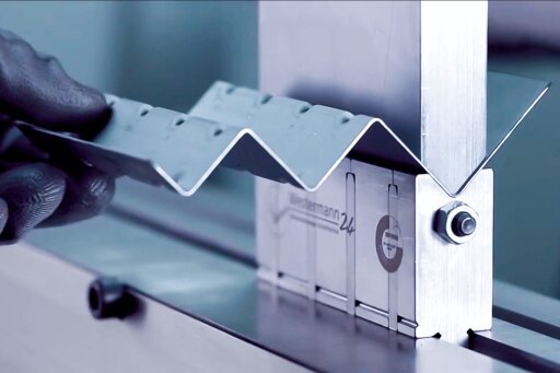
Metal bending is the process of transforming a flat sheet into a specific angle or shape by applying force through a punch and die. During bending, the metal stretches on one side and compresses on the other, forming bends or folds. This process turns 2D cut parts into 3D structures commonly used for brackets, enclosures, and frames.
During prototyping, bending provides engineers with an early indication of how a design will perform in real-world use. They can check fit, clearance, and load-bearing capability. Bending also helps reveal design flaws—such as poor bend radii or poorly placed holes—before mass production begins. Solving these problems early saves both time and cost.
Tolerances and Design Considerations in the Early Stage
Accurate bending starts with a well-defined design. Even slight variations in angle or bend radius can affect how parts fit together. Designers should set practical tolerances based on the chosen bending method and the material used.
Material thickness, bend allowance, and K-factor all influence accuracy. Thicker sheets often require larger bend radii to prevent cracking, while thinner sheets can achieve tighter bends. Holes or cutouts placed too close to the bend line may distort or tear during the forming process.
In the early prototype phase, it’s best to keep designs simple and focus on functional testing rather than visual perfection. Once the design proves reliable, tolerances can be tightened for production. This approach allows prototypes to transition smoothly into manufacturing while maintaining both quality and efficiency.
Main Metal Bending Methods Explained
Selecting the proper bending method is critical during prototyping. Each method has its advantages and limitations, depending on the material, part geometry, and precision required.
Servo Press Brake Bending
A servo press brake uses a servo motor to drive a screw or ball screw, precisely controlling the slider’s position and speed. The servo system provides real-time feedback and closed-loop control, automatically adjusting output based on load changes to ensure consistent accuracy and stability.
Servo press brake bending offers fast operation, low cost, and easy adjustment—making it ideal for prototypes that require small design changes. It’s suitable for thin to medium-thickness sheets and can achieve multiple bend angles with a single die. However, springback may occur, requiring slight over-bending to maintain precision. For very thick plates or parts that demand tight tolerances, air bending precision may be limited.
Hydraulic Press Brake Bending
A hydraulic press brake utilizes a hydraulic system to pressurize oil through a pump, driving pistons to move the ram up and down for bending operations. The system controls flow and pressure through proportional or servo valves to regulate slider speed and position.
Hydraulic bending is ideal for small batches or prototypes requiring complex bends. It handles thick materials well and ensures consistent angles across multiple bends. However, it takes longer to adjust tooling compared to air bending and may cause faster tool wear.
Rotary Draw Bending
Rotary draw bending wraps the sheet or tube around a rotating die to form smooth, consistent curves. It’s suitable for ductile metals such as aluminum, copper, and mild steel.
This method is commonly used for tubes, cylinders, and tubular structures. It offers precise control over bend radius and maintains uniform wall thickness, making it ideal for frames, handrails, and tubular brackets. CNC rotary draw-bending machines can even produce complex shapes with multiple curves.
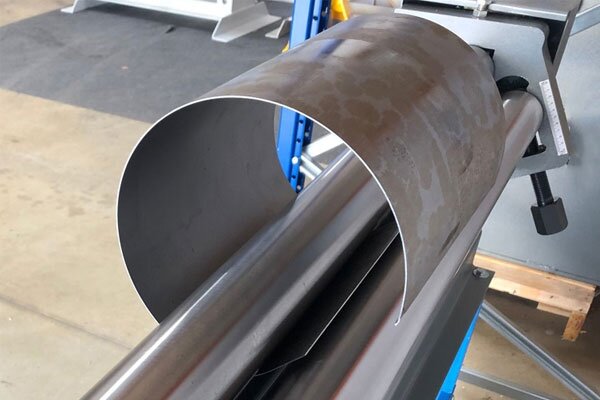
Roll Bending
Roll bending passes a sheet or plate through three rollers to gradually form large-radius bends. The stress is evenly distributed, reducing the risk of cracking or deformation.
This method works well for prototypes that require cylinders, cones, or curved panels—such as tanks, covers, or air ducts. It can handle large sheets that are difficult to bend on a press brake. By adjusting the roller spacing, operators can precisely control the bend radius, making it a flexible option for both complex and straightforward curved parts.
Choosing the Right Bending Solution for Prototypes
Selecting the proper bending method is crucial for ensuring a smooth prototype development process. Each technique has its own advantages depending on material type, part complexity, and precision requirements.
Material Thickness and Type
The first factor to consider is the material. Thin sheets, such as aluminum or mild steel, can be easily bent using manual or CNC press brakes. These materials are well-suited for fast adjustments and cost-effective testing.
For thicker or harder metals, such as stainless steel or titanium, more powerful bending equipment is required. CNC press brakes equipped with proper tooling can bend these materials without cracking or excessive springback. For very thin or fragile materials, laser bending or air bending may be used since they apply less force and minimize deformation.
Bend Radius and Complexity
The bend radius directly affects part strength and appearance. Smaller radii create sharper bends but increase the risk of cracking in harder materials.
For parts with multiple bends, complex angles, or tight tolerances, CNC press brakes offer the most precise control. Each bend angle and sequence can be accurately programmed. For curved or more intricate shapes, roll bending or stretch forming may be used to achieve the required design.
Tolerance and Repeatability Requirements
As prototypes approach the final design stage, maintaining consistent tolerance and repeatability becomes essential. Even minor deviations in bend angle can affect assembly fit, especially when multiple parts must align precisely.
CNC press brakes ensure accuracy by controlling programmed angles, back gauges, and pressure during each bend.
Repeatability is also critical when producing multiple prototypes for testing or client review. A reliable bending process ensures consistent results, reduces rework, and speeds up feedback. This reliability makes CNC press brake bending one of the preferred choices for high-quality sheet metal prototypes.
Press Brake Bending: The Best Metal Bending Solution
Press brake bending is widely recognized as the most efficient and adaptable method for prototype fabrication. It can handle various materials, thicknesses, and bend types while maintaining short setup times. This makes it ideal for rapid design testing and small-batch production.
Why Press Brakes Dominate Prototype Fabrication?
Press brakes excel because they can meet nearly all project requirements. Whether bending thin aluminum brackets or thick stainless-steel panels, they deliver accurate angle control and repeatability. Engineers can easily modify bend sequences, adjust angles, or change tooling setups to quickly test different design iterations.
Their versatility also comes from the wide range of available dies and punches. Press brakes can perform V-bends, U-bends, offset bends, and hems. Unlike stamping or roll forming, which require custom tooling, press brakes need only minor tool changes. This reduces both cost and lead time.
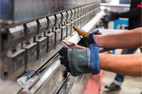
Setup Process and Tooling Flexibility
The setup process of a press brake is quick and straightforward. Engineers can use standard tooling to complete everyday bending tasks, avoiding the need for costly custom dies. The setup involves selecting the appropriate upper and lower dies, determining the bending angle, and adjusting the back gauge to ensure accuracy.
Modern press brakes equipped with digital controls make setup even more convenient. Operators can program bending sequences, store parameters, and adjust settings between batches to optimize production efficiency. For prototypes with multiple bend angles or minor batch variations, this feature saves time and reduces errors.
Tooling flexibility is another significant advantage. The upper and lower dies can be replaced within minutes to accommodate different material thicknesses and product designs. This allows teams to test new designs without interrupting production or creating new custom tooling, thereby helping to lower costs.
This adaptability is one of the key reasons press brakes remain the core equipment for precision bending and forming operations.
Precision and Quality in Prototyping Bends
Even minor bending errors can cause misalignment, weak points, or assembly issues in prototypes. By controlling factors such as springback, tooling alignment, and material properties, engineers can achieve consistent and high-quality bending results.
How to Avoid Springback and Cracking?
Springback occurs when a metal tries to return to its original shape after bending, causing the final angle to open slightly. To compensate, engineers typically over-bend the sheet by about 5–10%.
For example, to achieve a final 90° bend, the sheet may need to be bent to 94.5–99°.
Material selection significantly affects the degree of springback. Aluminum alloys, such as AL5052, typically exhibit approximately 2% springback, whereas harder metals like 304 stainless steel can achieve 5% or more. Controlling bending speed and pressure also helps maintain consistency.
Cracking often occurs when the inside bend radius is too small. A standard guideline is to keep the inner radius at least equal to the sheet thickness for steel, and twice the thickness for aluminum.
For instance, a 1.5 mm aluminum sheet should have a minimum inner radius of 3 mm. A smaller radius increases the risk of cracking. Harder aluminum grades, such as AL6061 and AL6063, are more prone to cracking during bending and are generally not recommended for tight bends.
Importance of Proper Tooling Selection
Using punches or dies that don’t match the sheet thickness or bend radius can cause scratches, angle distortion, or cracks. As a general rule, the die opening should be 4 to 8 times the sheet thickness. For example, a 1.5 mm sheet would require a V-die opening of 6–12 mm.
For harder materials or sheets thicker than 3 mm, a slightly larger opening helps reduce the risk of cracking. For products with high surface appearance requirements, protective films or rubber pads can be used to prevent surface marks during bending.
Special radius dies are useful for thicker sheets or larger bends, helping reduce stress concentration.
Regular die maintenance—such as cleaning, alignment checks, and replacing worn tooling—ensures consistent and reliable bending results over time.
Bring Your Sheet Metal Prototype to Life
Ready to turn your sheet metal design into a functional, production-ready prototype?
Our engineering team delivers high-precision, high-quality bends with fast turnaround and tight tolerances. From initial design to full-scale production, we provide expert support at every stage to ensure your project meets both performance and quality goals.
Contact us today to discuss your project or request a quick, no-obligation quote. Let’s build your next prototype with precision, reliability, and confidence.
Hey, I'm Kevin Lee

For the past 10 years, I’ve been immersed in various forms of sheet metal fabrication, sharing cool insights here from my experiences across diverse workshops.
Get in touch
Kevin Lee
I have over ten years of professional experience in sheet metal fabrication, specializing in laser cutting, bending, welding, and surface treatment techniques. As the Technical Director at Shengen, I am committed to solving complex manufacturing challenges and driving innovation and quality in each project.
Related Resource

Fingerprint Resistant Stainless Steel: How It Works,and How to Choose


