The rapid rise of electric vehicles (EVs) and energy storage systems (ESS) is reshaping how industries think about thermal management. As battery energy density continues to climb, the ability to control temperature with precision has become a defining factor for battery reliability and lifespan.
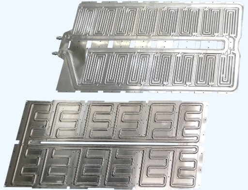
Among various cooling methods, sheet metal battery cooling plates have emerged as a leading solution for high-performance packs. They combine excellent thermal conductivity, lightweight structure, and cost-effective scalability.
This article explores how sheet-metal battery-cooling plates are designed, manufactured, and integrated—and why they are critical to the next generation of battery innovation.
What Are Battery Cooling Plates?
A battery cooling plate is a precision-engineered metal component designed to draw heat away from battery cells and transfer it into a flowing coolant, usually a water-glycol mixture. It acts as both a thermal bridge and a mechanical support within the battery pack.
Most designs consist of two thin aluminum or copper sheets, typically 1–3 mm thick, welded or brazed to create enclosed flow channels. Coolant circulates through these channels, absorbing heat evenly from the battery cells and maintaining the entire pack within the optimal temperature window — usually between 20 °C and 40 °C.
Cooling plates play four critical roles:
- Maintain uniform temperature across all cells to prevent imbalance.
- Extend cycle life by avoiding thermal stress and hotspots.
- Increase power output during fast charging or heavy load conditions.
- Enhance safety, reducing the risk of thermal runaway.
To visualize their impact: a 1 mm aluminum plate transfers heat 20× faster than air, providing immediate and stable cooling even during rapid charging.
The Role of Cooling Plates in Battery Thermal Management
Efficient design begins with choosing the right materials and internal structure. The combination of metal type, surface treatment, and flow-channel geometry defines both performance and durability of a cooling plate.
How Battery Heat Is Generated?
During operation, lithium-ion cells convert electrical energy into heat through ohmic resistance and electrochemical reactions. A typical 50 kWh EV pack running at a 2C discharge rate can generate 1.5–2 kW of heat continuously. If that heat isn’t dissipated, local temperatures can exceed 60 °C, causing electrolyte degradation, lithium plating, and irreversible capacity loss.
Sheet metal cooling plates are designed to keep the temperature rise under 5 °C, even under sustained load. By maintaining this narrow thermal window, engineers can extend pack life by up to 30 %, reduce failure rates, and ensure consistent energy output over thousands of cycles.
Why Thermal Uniformity Matters?
The real challenge isn’t just removing heat — it’s removing it evenly. Uneven temperatures across cells create performance drift and accelerate aging. Studies show that when the temperature variation in a module drops from ±5 °C to ±2 °C, the pack’s usable life can increase by nearly 25–30 %.
Uniform heat removal also improves charging stability and state-of-charge (SOC) accuracy, as the BMS relies on consistent thermal data to balance cells correctly. Thus, cooling plates aren’t just components — they are precision tools for energy balance.
Air Cooling vs. Liquid Cooling: The Efficiency Gap
Air cooling is simple but limited. Air’s low thermal conductivity (≈0.026 W/m·K) restricts heat transfer, making it unsuitable for dense or high-power packs. In contrast, liquid cooling with water-glycol mixtures (≈0.6 W/m·K) offers over 20× greater efficiency, providing stable temperature control under fast-charging and continuous high-load conditions.
| Cooling Method | Thermal Conductivity (W/m·K) | Typical Temperature Gradient (°C) | Ideal Application |
|---|---|---|---|
| Air Cooling | 0.026 | 10–20 | Low-power or hybrid systems |
| Liquid Cooling | 0.6 | 2–5 | EVs, ESS, high-density modules |
In most modern EVs, liquid-cooled sheet-metal plates are the standard because they deliver high uniformity, durability, and modular scalability at a reasonable cost.
The Engineering Advantage of Sheet Metal Cooling Plates
Sheet metal offers several structural and manufacturing advantages:
- Lightweight construction reduces vehicle weight while maintaining stiffness.
- A high surface area-to-volume ratio improves heat transfer.
- Flexible design options enable serpentine, parallel, or pin-fin channel layouts.
- Scalable production fits both prototype and mass manufacturing needs.
Materials and Structural Design for Sheet Metal Cooling Plates
Efficient design begins with choosing the right materials and internal structure. The combination of metal type, surface treatment, and flow-channel geometry defines both performance and durability of a cooling plate.
Common Metals Used
The choice of metal directly determines how efficiently a cooling plate transfers heat and withstands long-term stress. Aluminum and copper remain the two dominant materials, each offering unique trade-offs between conductivity, weight, and cost.
| Material | Thermal Conductivity (W/m·K) | Density (g/cm³) | Cost Index (≈) | Corrosion Resistance | Typical Application |
|---|---|---|---|---|---|
| Aluminum (3003, 6061) | 180–210 | 2.7 | ★★☆ | High | EV battery plates, energy storage systems |
| Copper | 385–400 | 8.9 | ★★★ | Medium | High-performance or compact modules |
| Stainless Steel (304) | 15–25 | 7.9 | ★☆☆ | Excellent | Marine or corrosive environments |
Aluminum dominates EV cooling systems because it offers light weight, excellent corrosion resistance, and cost-effective formability. Copper, while providing nearly double the thermal conductivity, is heavier and more expensive — used mainly where high heat flux or space constraints demand extreme performance.
Surface Treatments and Corrosion Protection
Cooling plates continuously contact glycol-based coolants, so corrosion protection is critical to prevent internal leakage and particle contamination. The most effective surface treatments combine chemical stability with bonding compatibility for thermal interface materials (TIMs).
Common treatments include:
- Anodizing: Forms a hard, oxide layer on aluminum that resists corrosion and enhances heat spreading.
- Nickel or Chromate Plating: Adds a barrier layer that protects against galvanic corrosion when paired with dissimilar metals.
- Epoxy or Passivation Coatings: Used in extreme humidity or marine applications for additional protection.
Testing shows anodized aluminum plates retain over 95% of their thermal conductivity after 1,000 hours of salt-spray exposure — far outperforming untreated plates. Well-applied coatings not only extend service life but also improve coolant purity, thereby reducing maintenance costs in the long term.
Flow Channel and Plate Structure Design
The internal channel geometry defines how effectively the coolant absorbs and distributes heat across the plate. Designers use Computational Fluid Dynamics (CFD) simulations to optimize this balance between temperature uniformity, pressure drop, and coolant velocity.
Serpentine Flow Channels
- A single continuous path that ensures complete coverage of the surface.
- Delivers excellent thermal uniformity but higher pressure loss.
- Ideal for compact EV modules and battery packs under fast-charging cycles.
Parallel Flow Channels
- Multiple flow paths allow lower pressure drop and faster flow.
- Simpler manufacturing and scalability.
- Requires careful balancing to prevent uneven flow distribution.
Pin-Fin or Dimple Structures
- Small 3D protrusions inside channels increase turbulence, boosting heat transfer by 10–15%.
- Typically formed by hydroforming or CNC embossing.
- Best for high-power-density applications where surface area is crucial.
In EV applications, target flow rates typically range from 2–4 L/min per module, with a temperature rise of less than 3 °C between the inlet and outlet. CFD analysis also ensures the pressure drop remains below 20 kPa, minimizing pump energy consumption while achieving uniform cooling.
Design Parameters and Thickness Optimization
Cooling plates are generally built from two sheets, 1.0–3.0 mm thick. Thinner plates provide better heat transfer but risk deformation under pressure, while thicker plates increase stiffness but add weight.
Engineers use Finite Element Analysis (FEA) to simulate internal pressure loads — often up to 0.3 MPa — and identify areas requiring reinforcement ribs or adjustments to weld spacing.
A well-optimized plate achieves:
- Flatness tolerance: within ±0.05 mm
- Burst pressure: over 1 MPa
- Thermal resistance: below 0.20 °C/W
This precision ensures the plate stays flat and leak-free even after 10,000+ pressure cycles, critical for high-voltage battery modules where sealing integrity is non-negotiable.
Manufacturing Tolerances and Surface Flatness
Effective heat transfer relies on tight control of surface flatness and channel geometry. Even small irregularities can increase thermal resistance and reduce efficiency.
Best practices include:
- Controlling flatness within ±0.05 mm using precision clamping during welding.
- Minimizing weld bead distortion through controlled heat input and cooling rates.
- Applying thermal interface materials (TIMs) like gap fillers or pads to bridge microscopic air gaps.
Improving surface flatness from 0.10 mm to 0.05 mm can reduce interface resistance by nearly 25%, enhancing overall temperature uniformity.
Manufacturing Processes of Sheet Metal Cooling Plates
Transforming a digital design into a durable, leak-proof, and thermally efficient cooling plate demands precision at every stage. From sheet forming to welding, each step must preserve geometry, prevent distortion, and ensure consistent performance across thousands of units.
Forming and Channel Creation
The process begins with two sheets of aluminum or copper, typically 1–3 mm thick. Depending on production volume and design complexity, manufacturers use several forming methods:
Precision Stamping
- Ideal for high-volume production.
- Provides consistent depth and channel curvature within ±0.1 mm tolerance.
- Works best for simple serpentine or parallel flow layouts.
CNC Machining
- Suitable for prototyping or low-volume runs.
- Allows full design flexibility with channel depths up to 3 mm and complex geometries.
- Ensures high repeatability for early-stage validation or design customization.
Hydroforming
- Uses high-pressure fluid to form evenly spaced channels across the sheet.
- Reduces residual stress and delivers smooth internal surfaces for better coolant flow.
- Preferred in EV applications requiring compact, high-density plates.
Joining and Sealing Processes
Once the channel layer is formed, the two sheets are joined to create a sealed internal network. The choice of joining process affects thermal efficiency, weight, and production cost.
| Process | Characteristics | Advantages | Typical Use Case |
|---|---|---|---|
| Laser Welding | Uses focused beams to melt and fuse sheets along predefined seams. | High precision, minimal distortion, clean seams. | Thin aluminum or copper plates. |
| Friction Stir Welding (FSW) | Joins sheets by mechanical stirring below melting point. | Strong joints, no filler, minimal porosity. | High-pressure systems and structural plates. |
| Vacuum Brazing | Fuses sheets using filler metal in a vacuum furnace. | Excellent sealing and conductivity; no oxidation. | Complex, multi-channel plates. |
| TIG/MIG Welding | Manual or semi-automatic arc welding. | Flexible for prototypes or repairs. | Small-batch fabrication. |
Among these, laser welding dominates due to its combination of precision and speed. A laser seam width of 0.4–0.8 mm can maintain high flatness and withstand internal pressures above 1 MPa.
FSW is also gaining popularity for structural applications because it eliminates filler materials and produces joints with 30% higher fatigue life compared to conventional welds.
Leak Testing and Quality Verification
After joining, each cooling plate undergoes rigorous leak and strength testing to ensure reliability in real-world operation.
Helium Leak Detection
- Detects microleaks as small as 1×10⁻⁶ mbar·L/s using mass spectrometry.
- Used for EV-grade plates that require 100% sealing integrity.
Air Pressure and Submersion Test
- The plate is filled with air and submerged in water at 0.3–0.5 MPa to check for visible bubbles.
- Simple and effective for production-level checks.
Pressure Cycling and Burst Test
- Simulates continuous heating and cooling under working pressures.
- A standard test may involve 10,000 pressure cycles and a burst pressure of over 1.2 MPa.
Plates that pass all tests are cleaned, dried, and marked with serial numbers for full traceability, ensuring compliance with ISO 9001 and automotive PPAP documentation standards.
Conclusion
Sheet metal cooling plates have evolved from simple heat exchangers into integrated thermal-management modules. Their lightweight structure, manufacturability, and ability to maintain temperature uniformity make them indispensable to modern EV and ESS systems.
Ready to Optimize Your Battery Thermal System? At Shengen, our engineering team specializes in custom sheet-metal battery-cooling plate fabrication—from prototype validation to high-volume production. Upload your CAD files or contact our engineers to discuss how we can support your next EV or energy-storage project.
Hey, I'm Kevin Lee

For the past 10 years, I’ve been immersed in various forms of sheet metal fabrication, sharing cool insights here from my experiences across diverse workshops.
Get in touch
Kevin Lee
I have over ten years of professional experience in sheet metal fabrication, specializing in laser cutting, bending, welding, and surface treatment techniques. As the Technical Director at Shengen, I am committed to solving complex manufacturing challenges and driving innovation and quality in each project.
Related Resource

Fingerprint Resistant Stainless Steel: How It Works,and How to Choose


