Many engineers and buyers run into quality problems with rotating parts—vibration, wobble, or inconsistent fit. The cause often traces back to geometric tolerances. Specifically, circular runout and total runout. These two GD&T controls seem similar, but solve different problems. If you mix them up, parts may not work as planned.
Circular runout controls variation at each circular cross-section. Total runout controls the entire surface across the length. Circular runout focuses on roundness at one spot. Total runout adds straightness and taper checks across the whole feature.
Please stick with me for simple callout rules, gauge setups, and real numbers for standard sizes. You will avoid scrap and guesswork, pass audits, and keep your line moving daily.
What is Geometric Dimensioning and Tolerancing (GD&T)?
GD&T is a way to control the shape and position of parts. It sets clear limits so that parts fit together and move as intended.
Instead of only giving numbers for size, GD&T also defines how straight, flat, or round a surface must be. It uses symbols on technical drawings to show these limits.
Runout is one type of tolerance in GD&T. It controls how much a rotating surface can move away from its correct path. When a shaft spins, it should turn smoothly. Runout checks for any wobble or shift. A dial indicator is used to measure this movement.
Runout is essential for parts that spin or fit closely with other parts. Too much runout can cause noise, extra wear, or even part failure.
What is Circular Runout?
Circular runout is a GD&T control for rotating parts. It limits how far a surface moves in and out at a single circular cross-section when the part turns about a datum axis. It combines roundness and alignment to that axis for that one section. This control applies to cylinders, cones, and faces.
It does not control taper, bow, or waviness along the axis. The stated tolerance equals the total indicator reading (TIR) allowed.
How is Circular Runout Measured?
Inspectors mount the part so it spins about a datum axis, often using centers, a collet, or V-blocks.
They place a dial indicator on the surface, perpendicular to the measurement direction. After zeroing the indicator, they rotate part one in a complete turn and record the difference between the highest and lowest readings. This difference is the TIR.
They repeat the process at each required location for checks at several sections. When checking a face, they position the indicator perpendicular to it near the radius necessary and follow the same steps.
Key Applications in Mechanical Components
Circular runout is common on bearing journals where smooth rotation is essential. It is also used on motor and pump shafts to reduce vibration and seal bores or gland diameters to keep even sealing contact. Brake disc faces, pulley grooves, and gear hubs may also require this control to lower noise and wear.
Common Symbols and Drawing Representations
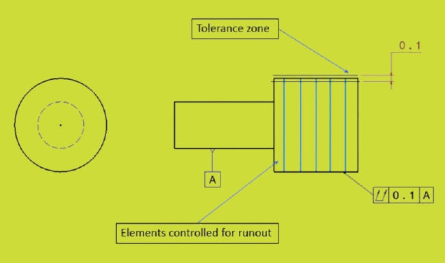
The drawings show the circular runout in a feature control frame with the circular runout symbol (a single circular arrow), the tolerance value, and the datum letter for the axis. Example: [runout symbol] | 0.02 | A.
A leader line points to the controlled surface. The tolerance zone is a band around each measured circle; no diameter symbol is used.
Runout uses RFS (regardless of feature size) by default. MMC or LMC modifiers are not applied.
If multiple sections need checking, the drawing may include a note such as “measure at multiple locations” or show gage points along the length.
What is Total Runout?
Total runout is a GD&T tolerance that limits surface variation when a part rotates about a datum axis. Unlike circular runout, which checks one cross-section at a time, total runout checks the whole surface in one measurement. It controls roundness, straightness, and taper at the same time.
The tolerance applies to every circular element and the length between them. It is stricter than circular runout and provides tighter control for critical parts.
How is Total Runout Measured?
To measure total runout, mount the part so it spins around its datum axis. Place a dial indicator against the surface. As the part rotates, slide the indicator from one end of the surface to the other.
Record the highest and lowest readings during the process. The total indicator reading (TIR) must stay within the stated tolerance. This method measures all variations together, showing how the whole surface performs, not just one section.
Key Applications in Rotating Parts
Total runout is used on precision shafts, spindles, and bearing fits. It is required when the entire surface’s shape and alignment must meet tight limits. Examples include turbine rotors, gearbox shafts, and automotive crankshafts. Using total runout here helps prevent imbalance, vibration, and noise.
Common Symbols and Drawing Representations
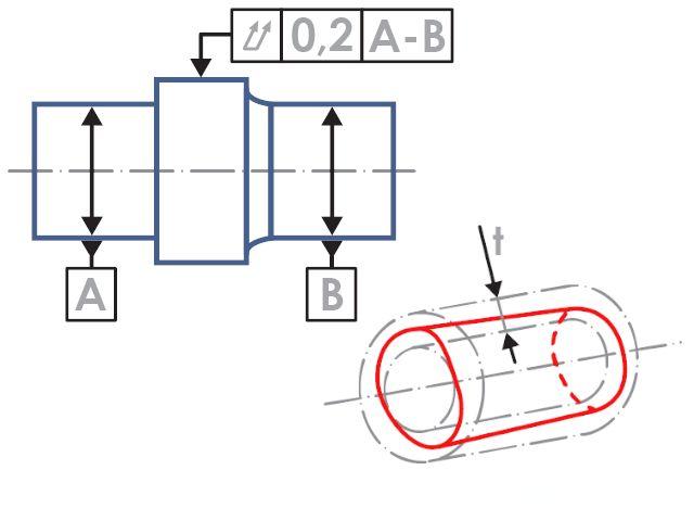
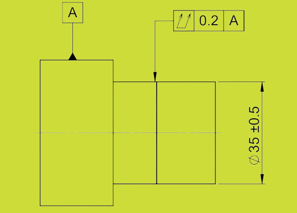
On drawings, total runout is shown in a feature control frame with the total runout symbol (two concentric arrows), the tolerance value, and the datum letter. Example: [double arrow symbol] | 0.01 | A.
It is usually applied to cylindrical surfaces. The tolerance zone is a 3D band surrounding the full length of the surface, aligned with the datum axis. Like circular runout, it defaults to RFS (regardless of feature size) and does not use MMC or LMC modifiers.
Use total runout when you need complete surface control, not just measurements at a few points.
Core Differences Between Circular Runout and Total Runout
Circular runout and total runout may seem similar, but they control different features of a part. Understanding these differences helps you choose the proper control for your design or inspection.
Measurement Scope and Surface Coverage
Circular runout measures one cross-section at a time. It does not account for the surface shape between sections. Measurements are taken at specific points only.
Total runout measures the entire surface along the length of the part. It includes roundness, straightness, taper, and waviness. This provides complete surface control rather than checking at isolated spots.
Impact on Part Functionality
Circular runout keeps a part round at given points. It reduces wobble but does not control taper or bow.
Total runout ensures the part stays true along its whole length during rotation. It prevents runout issues over the entire surface, reducing the risk of noise, wear, or leaks. Use total runout when every point on the surface must stay closely aligned to the datum.
Inspection Methods and Tools
Both controls use a dial indicator and a rotary fixture. The indicator remains fixed at one location while the part spins for circular runout. The indicator moves along the surface for total runout as the part rotates, recording variations over the length.
Both methods require stable fixturing. The part must spin accurately around the datum axis. V-blocks, centers, or a lathe can help hold it steady.
Tolerance Zone Differences
The tolerance zone is a 2D circle at each measured cross-section in circular runout. The surface must remain within this circle during rotation.
The tolerance zone is a 3D cylindrical band covering the full length of the total runout. The surface must stay within this band at all points.
The total runout zone is more restrictive because it includes all variations along the length. This makes total runout a stricter and more comprehensive control.
Factors Affecting Runout Accuracy
Runout readings can change based on how the part is held, the machine used, and the environment. To get accurate results, control these factors during inspection.
Workpiece Mounting and Clamping Errors
Runout values will be off if the part is not centered or clamped evenly. Soft jaws, uneven pressure, or dirty contact surfaces can shift the part slightly.
Even small shifts cause significant reading changes. Always mount parts using accurate fixtures. Clean mating surfaces and use repeatable setups to reduce false readings.
Machine Tool Spindle Accuracy
The machine spindle must rotate smoothly. If the spindle wobbles or has wear, it adds extra runout. This makes it hard to tell if the error comes from the part or the machine.
Check spindle accuracy before testing parts. Use a reference gage or master part to confirm machine stability.
Surface Finish and Imperfections
Rough surfaces or burrs affect the dial indicator’s contact. A bump or dip can cause false peaks in the reading.
Clean the surface before measuring. Remove burrs, rust, and chips. Use a probe with a larger contact tip for rough parts to average out minor flaws.
Environmental Factors like Temperature and Vibration
Room temperature changes can expand or shrink the part. Even a few degrees can shift the surface.
Vibrations from nearby machines can shake the test setup. This adds noise to the reading. Use stable tables and test in a quiet spot. Let parts reach room temperature before testing.
Best Practices for Specifying Runout on Drawings
Clear and practical runout callouts reduce part failures, lower costs, and improve production efficiency. The tips below can help achieve better results.
Selecting the Right Tolerance for the Application
Choose circular runout when roundness at specific sections is enough. It works well for simple shafts, bearing seats, and brake discs.
Use total runout when the entire surface must remain aligned and smooth. It is suitable for long shafts, spindles, and parts with tight seal fits.
Match the tolerance type to the part’s function. Avoid using total runout when circular runout will do the job. This prevents extra work and cost without added benefit.
Avoiding Overly Tight Tolerances
Tolerances that are too tight increase manufacturing costs and may slow production. Shops may need higher-precision equipment or longer setup times to meet extreme requirements.
Start with a realistic value. Review similar parts or test samples to confirm the tolerance needed. If 0.05 mm works without issues, there is no need to specify 0.01 mm.
Communicating with Suppliers and Inspectors
Add notes on the drawing to explain the inspection method or measurement location. Include gage points, surface finish requirements, or part orientation if they affect results.
Discuss tolerances with your supplier before finalizing the drawing. Confirm they have the tools and processes to measure and meet the requirements.
Share both 2D and 3D CAD files, and ask for feedback early. This avoids delays, reduces misunderstandings, and ensures the part meets the drawing and real-world performance needs.
Conclusion
Circular runout checks roundness at single cross-sections. Total runout controls the entire surface along its length. Circular runout is more straightforward and suitable for checking wobble at specific points. Total runout is stricter and better for high-precision rotating parts. Each has its place in GD&T, depending on part function and inspection needs.
Looking for expert support with tight runout tolerances or need parts that meet your exact specs? Contact us today. Our team can help you find the right solution for your project.
Hey, I'm Kevin Lee

For the past 10 years, I’ve been immersed in various forms of sheet metal fabrication, sharing cool insights here from my experiences across diverse workshops.
Get in touch
Kevin Lee
I have over ten years of professional experience in sheet metal fabrication, specializing in laser cutting, bending, welding, and surface treatment techniques. As the Technical Director at Shengen, I am committed to solving complex manufacturing challenges and driving innovation and quality in each project.
Related Resource

Fingerprint Resistant Stainless Steel: How It Works,and How to Choose


