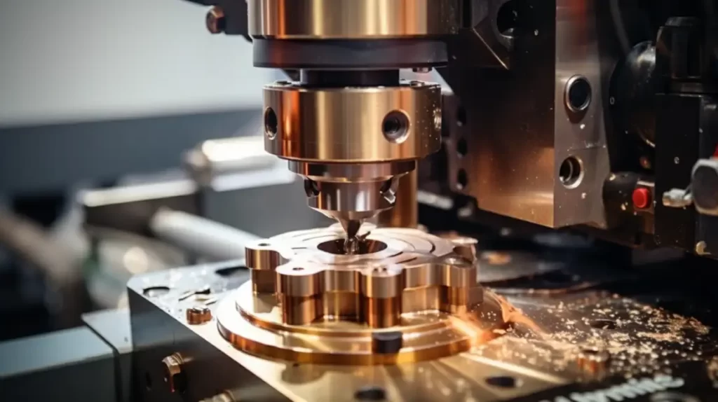
In low-volume work, drilling brass rarely causes issues. But when a job moves into batch CNC production, brass can become surprisingly unpredictable.
The risks usually do not come from material hardness. In our experience, scrap and downtime in brass production runs stem from mismatches in tool geometry, poor chip control, and inconsistent breakthrough behavior.
If these variables are not evaluated during process engineering, it often leads to tool wander, excessive deburring workloads, and interrupted machine cycles. This article covers the specific factors we evaluate to keep brass drilling stable across high-volume runs.
Why Brass Still Causes Trouble in Production?
Because brass machines so easily, jobs are often set up with generic tooling and baseline parameters. This is where process drift usually starts. The problems rarely show up on the first piece; they compound over the life of the batch as tooling and chip dynamics change.
Easy to cut, easy to lose control
The primary risk is the material’s softness combined with standard positive-rake twist drills. Instead of cutting smoothly, standard drills often grab the material, pulling themselves into the cut faster than the programmed feed.
This sudden spike in tool load destabilizes the process, especially if the fixture cannot handle the upward pull. This is why standard off-the-shelf drill geometry rarely survives a long brass production run without modification.
Where does scrap start in brass drilling?
When scrap happens in brass drilling, it is rarely a horsepower or rigidity issue. It is usually a loss of control at the cutting edge.
A drill that grabs or deflects even slightly will often produce bell-mouthed holes, out-of-tolerance diameters, or torn internal finishes. This risk scales up quickly with the hole depth-to-diameter ratio, the angle of the breakthrough, and the effectiveness of coolant reaching the cutting zone. What passes a first-article inspection can easily drift out of spec by the hundredth part if the cutting dynamics are not stable.
How does drill instability hurt yield and delivery?
In production execution, an unstable drill results in lost spindle time. If an operator has to babysit a machine to clear wrapped chips or listen for chatter, unattended runtime drops to zero.
Furthermore, the shock of a drill grabbing often chips carbide margins. This unpredictable tool wear requires more frequent offset adjustments, increasing the in-process inspection workload. Ultimately, managing these micro-stoppages is often the difference between hitting a delivery schedule and fighting a backlog of rework.
C360 vs. C260: Different Alloys, Different Drill Strategy
Assuming all brass will machine the same is a common trap in production planning. The specific alloy dictates chip behavior and edge loading, which means the CNC programming strategy must adapt to maintain stability.
C360 (Free-Machining): higher feeds and short chip control
C360 is highly forgiving. It naturally breaks into short, granular chips that evacuate easily through the flutes.
Because chip packing is rarely the bottleneck, we can usually increase feed rates. Depending on hole depth and coolant pressure, C360 often allows for drilling to depth in a single pass without retracting. The main judgment call here is maximizing throughput without sacrificing surface finish or overheating the tool.
C260: tougher chip flow and higher burr risk
C260 behaves entirely differently on the spindle. It is highly ductile and tends to form long, continuous chips. These chips will quickly pack the flutes or wrap around the tool holder if not actively managed.
Additionally, this ductility means C260 is far more likely to roll over at the hole exit, creating heavy burrs. If not anticipated during programming, this significantly increases the manual deburring workload and the risk of scrapped parts during downstream assembly.
How does alloy choice change the tool load and edge condition?
The clean shearing of C360 generally keeps temperatures manageable and tool life highly predictable. C260, however, generates more friction and introduces a much higher risk of Built-Up Edge (BUE).
Once brass micro-welds to the drill margin, hole size control is lost. Preventing BUE in C260 usually requires stricter coolant concentration monitoring and more conservative surface speeds to protect the hole finish.
Matching the drill strategy to the brass grade
Cycle selection must match the chip form. For C360, standard G81 drilling cycles are often sufficient, provided the feed rate is high enough to maintain a stable chip load.
For C260, chip control dictates the program. We typically rely on peck drilling cycles (G73 or G83) strictly to force chip breakage. The peck depth and retract strategy are judged case-by-case, depending heavily on the hole diameter and the depth of coolant penetration required to clear the flutes.
Tool Geometry That Reduces Grab and Stabilizes the Cut
In volume brass production, off-the-shelf drill bits are rarely a reliable baseline. Using generic tool geometry is a common reason a stable setup begins producing out-of-tolerance holes mid-batch. Controlling the cutting edge is usually the most effective way to prevent tool pull-in, limit wander, and manage exit burrs.
Point geometry that limits pull-in
Standard twist drills are manufactured with a positive rake angle, designed to shear materials such as steel. In brass, this geometry often acts like a screw thread, pulling the tool into the workpiece faster than the machine’s feed rate.
To prevent unpredictable self-feeding, the cutting lips are usually modified. Preparing the drill with a “dubbed” edge—a small flat ground onto the cutting lip—creates a zero or slightly negative rake. This shifts the cutting dynamics from aggressive slicing to a more controlled scraping action, helping stabilize the tool load even when the material yields inconsistently.
Why do overly sharp edges create instability?
While a razor-sharp edge seems ideal, it is fragile in a production environment. In brass, an overly sharp positive edge is not only prone to grabbing, but the resulting micro-vibrations can quickly chip the cutting edge, especially on carbide tools.
Once the edge breaks down, the hole continues to degrade rapidly. A chipped tool begins pushing material rather than cutting it, which tends to drastically increase burr size at the hole exit and drive up deburring workloads.
Split points, edge prep, and margin control
Positional accuracy depends heavily on how the drill enters the material. A standard chisel edge tends to walk before it bites, consuming positional tolerance before the hole is even started.
Using a 135-degree split point helps center the tool and lowers the initial thrust force. Additionally, controlling the drill margin width is important on longer runs. A wider margin provides better guidance in deep holes but increases friction, which can raise the risk of Built-Up Edge (BUE) if coolant access to the tip is limited.
When do straight-flute drills make sense?
For specific applications—particularly shallow holes or cross-holes in thin-walled parts—straight flute drills are often the most stable choice.
Because they lack a helix angle, the pull-in force is virtually eliminated. However, without a helix, they cannot efficiently lift chips out of the hole. They are typically restricted to depths where chip packing is not a primary risk, or used in conjunction with high-pressure through-tool coolant to force chips out.
Speeds, Feeds, and Coolant
Chasing maximum textbook surface speeds rarely solves hole quality issues in brass. While the material allows for highly aggressive parameters, the actual production limits are usually dictated by chip evacuation, surface finish requirements, and spindle stability.
Starting SFM ranges for brass drilling
With standard High-Speed Steel (HSS) tooling, starting surface speeds usually range from 150 to 300 SFM, while carbide tooling can run significantly faster. However, maximizing SFM is rarely the priority in batch work.
Running at maximum speed increases heat generation at the drill margin, which raises the risk of BUE and premature tool wear. In many production runs, scaling back the surface speed slightly can significantly extend tool life and keep the process stable for a full shift without operator intervention.
Feed strategies for chip control and hole finish
Feed rate is the primary lever for controlling chip shape. A common mistake is using a light feed to “play it safe.” In brass, an overly light feed often causes the drill to rub rather than cut.
This rubbing generates friction, hardens the hole walls, and results in poor surface finishes. Pushing a heavier, consistent feed keeps the cutting edge fully engaged, helps fracture the chip (especially in C360), and pushes heat into the chip rather than the workpiece.
When peck cycles help and when they waste time
Using a full-retract peck cycle (G83) on every brass hole wastes valuable unattended runtime by causing unnecessary air-cutting. If the alloy is C360 and the hole depth-to-diameter ratio is low, drilling in a single pass is usually preferred.
Pecking typically becomes necessary when running highly ductile alloys like C260, or when the hole depth prevents chips from clearing naturally. In those cases, short chip-breaking pecks (G73) are often used instead of full retracts to maintain chip control without severely impacting cycle time.
Coolant choices that support clean drilling
In brass drilling, coolant is relied upon more for lubricity and chip flushing than for pure temperature control. Getting the fluid directly to the cutting zone is essential to prevent chips from recutting and galling the hole walls. For deep features or high-volume runs, through-spindle coolant is often necessary to physically force chips back up the flutes and keep the drill point clear.
Why can active sulfur coolants stain brass?
This is a frequent oversight that leads to unexpected cosmetic scrap. Many heavy-duty cutting oils contain active sulfur to prevent welding in tougher metals.
However, active sulfur chemically reacts with copper, causing severe dark staining or tarnishing on brass parts. This can force an unplanned secondary cleaning operation. We typically verify that non-active coolants or specifically formulated water-soluble blends are used to protect the surface integrity of the brass parts throughout the run.
Holding Hole Quality Across Production Runs
A clean hole on a setup piece is a good start, but machining dynamics tend to drift over a batch of 5,000 parts. Managing this drift is usually the difference between a smooth run and a high rework rate.
Diameter variation and drill wander
As a drill progresses through a high-volume run, the cutting margins and chisel edge gradually wear. Depending on the tool wear pattern, hole depth, and coolant access, this wear can cause the hole diameter to shrink or cut slightly oversize.
A dull drill also requires greater thrust force to enter the material, increasing the risk of the tool walking before it bites and consuming positional tolerance early in the cycle.
Breakthrough and exit condition
Breakthrough quality often becomes harder to control as the shift goes on. As the cutting edge loses its sharpness, the tool tends to push the remaining material rather than shear it cleanly. This typically leads to burr growth at the hole exit, which can complicate downstream steps like tapping, plating, or assembly if it is not actively monitored.
When drilling is not enough?
Twist drills are not always the best tool for holding tight geometric tolerances across a full production run. If a print requires strict cylindricity, a tight bearing fit, or a highly accurate true position, relying only on a drill can increase the risk of variance.
In these cases, we typically use the drill strictly to evacuate bulk material, leaving a few thousandths of an inch of stock. Following up with a reamer or a boring bar to establish the final size and location is usually the more reliable approach for maintaining batch consistency.
How Shengen Helps Reduce Scrap and Keep Production on Schedule?
Transitioning a brass component from a single prototype to production volume is where manufacturing risks often compound. Our focus is on making that transition as stable as possible so the process scales without issues.
Exposing risks early in prototyping
We use prototype runs to do more than prove the part design; we use them to expose tooling, chip control, and breakthrough risks early. Identifying how a specific brass alloy behaves on the spindle during low-volume work helps us build a more resilient process for the production run.
Process planning and first-article validation
Before volume production begins, our process planning centers on alloy-specific machining strategies. We establish a reliable baseline through strict first-article validation, ensuring the chosen drill geometry, feed rates, and coolant setup can maintain tolerances over time.
In-process control and tool monitoring
Once a batch is running, keeping production on schedule comes down to execution. We rely on scheduled in-process checks and tool wear monitoring to catch process drift before it results in scrapped parts.
Struggling with drill wander, heavy burrs, or inconsistent tolerances on your brass components?
We solve these exact issues every day. With 10 years of CNC machining and sheet metal expertise, Shengen specializes in stabilizing unpredictable processes and taking projects seamlessly from prototype to mass production. Stop fighting rework and late deliveries. Send us your CAD file or drawing. Talk to an Engineering Expert Today.
Hey, I'm Kevin Lee

For the past 10 years, I’ve been immersed in various forms of sheet metal fabrication, sharing cool insights here from my experiences across diverse workshops.
Get in touch
Kevin Lee
I have over ten years of professional experience in sheet metal fabrication, specializing in laser cutting, bending, welding, and surface treatment techniques. As the Technical Director at Shengen, I am committed to solving complex manufacturing challenges and driving innovation and quality in each project.