Parts that require a tight fit, proper sealing, or precise alignment often need an accurate taper. Even a small mistake can cause a part to fail or not fit as intended. Taper turning is an important process for making parts with angled surfaces. This guide explains taper turning step by step, so you can achieve smooth, accurate results and avoid costly errors.
Taper turning is widely used in shafts, machine components, and assembled parts. It is also a common process in CNC lathe operations. In the following sections, we will look at how taper turning works and which method is best for your needs.
What Is Taper Turning in Machining?
Taper turning is the process of cutting a surface that gradually changes in diameter along the length of a round workpiece. It forms a cone-like shape using a lathe. The taper can be on the outside (external) or inside (internal) of the part. The angle and length of the taper are based on what the part is used for.
This method is often used when parts need to fit or align exactly—like shafts, pins, or tool holders. Tapers can be cut with manual or CNC lathes. Each type of machine has its way of setting up and controlling the cut.
Tapers are helpful because they make parts easier to position and lock in place. They are self-centering, provide a snug fit, and hold firmly under force. Tapers in tools allow for quick and repeatable mounting. In plumbing or gas lines, tapered threads help form strong seals.
How Does Taper Turning Work?
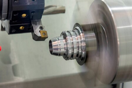
Taper turning works by moving the cutting tool at an angle to the workpiece axis while the part spins in the lathe. This angled movement makes the diameter change gradually along the length.
The process begins by securing the workpiece in the chuck or between centers. The machinist then sets the taper angle. This can be done with the compound rest, a taper attachment, or by offsetting the tailstock. On CNC lathes, the taper angle is entered directly into the program.
After the setup is ready, rough cuts remove most of the excess material. Lighter finishing cuts then bring the part to its final size. Accuracy is checked with tools like micrometers, calipers, or taper gauges. A smooth feed rate, sharp cutting edges, and proper spindle speed help produce a clean and precise surface.
Geometry of a Taper
Taper turning is not only about cutting material. It is about shaping the workpiece to a specific and accurate form. To do this well, you need to understand the basic geometry behind every taper.
Taper Angle and Its Measurement
The taper angle is the angle between the tapered surface and the workpiece axis. It is usually small and measured in degrees. Common measuring tools include a sine bar, a protractor, or a taper gauge.
Most tapers are symmetric, meaning the angle is the same on both sides. For example, if a part has a total included angle of 10°, each side will be 5° from the axis.
Taper Ratio Explained
The taper ratio describes how much the diameter changes over a given length. It is written as a ratio, such as 1:20. This means that for every 20 mm (or inches) of length, the diameter changes by 1 mm (or inch).
This ratio helps determine if a taper is steep or gradual. A steep taper, such as 1:10, is used for quick assembly or easy release. A shallow taper, such as 1:50, is better for accurate alignment.
Mathematical Formula for Taper Turning
Here is the basic formula for taper:
Taper = (D – d) / L
Where:
- D = Large diameter
- d = Small diameter
- L = Length of the taper
To find the angle in degrees:
Angle = arctangent[(D – d) / (2 × L)]
These calculations are useful for both setting up the cut and checking the finished part. They are also important for programming CNC machines with high accuracy.
Types of Taper Turning Methods
There are several ways to create a taper on a lathe. Each method fits different part lengths, angles, and accuracy needs. Here’s how each one works and when to use it.
Form Tool Method
This method uses a cutting tool that is ground to match the exact taper angle. The tool is fed directly into the rotating workpiece in a straight line. Because the tool already has the taper shape, it produces the angled surface in one pass.
Advantages:
- Very fast for small parts and short tapers.
- Simple setup with minimal adjustments.
Limitations:
- Only practical for short tapers because the entire taper must be formed in one cut.
- Creates high cutting forces, which can deflect the workpiece or tool.
- May reduce surface finish quality and shorten tool life due to heavy load.
Best For:
Small conical sections, chamfers, and high-volume production of short tapers.
Combining Feeds Method
In this method, both the longitudinal feed (along the axis) and the cross feed (toward the axis) are engaged simultaneously. The combined motion moves the tool diagonally, generating the taper.
Advantages:
- Can be used for both short and moderate-length tapers.
- Allows flexible adjustment of taper angle by changing feed rates.
Limitations:
- Hard to control manually because coordinating both feeds is challenging.
- Not common on manual lathes, but widely used in CNC turning where the tool path can be programmed accurately.
Best For:
CNC lathe operations, where software can precisely coordinate the tool’s diagonal movement.
Compound Rest Method
This is one of the most common techniques for manual lathes. The compound rest is rotated (swiveled) to the desired taper angle. The operator then uses the compound rest handwheel to feed the tool along that set angle while the workpiece rotates.
Advantages:
- Good for short and precise tapers.
- Easy to set and adjust angles.
- Provides good control over surface finish.
Limitations:
- Limited travel of the compound rest makes it unsuitable for long tapers.
- Slower than some other methods for larger parts.
Best For:
Short tapers, such as those used in tool shanks, center drills, and small alignment features.
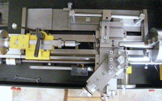
Taper Turning Attachment Method
This method uses a dedicated taper turning attachment mounted to the lathe. The attachment guides the tool holder at a preset angle while the carriage moves in a straight line along the lathe bed.
Advantages:
- Ideal for long tapers because the carriage movement is not restricted.
- Maintains the tailstock in normal position, avoiding alignment issues.
- Produces high accuracy with minimal setup errors.
Limitations:
- Requires a special attachment, which may not be available on all lathes.
- Slightly more time needed for setup compared to the compound rest method.
Best For:
Long and precise tapers, especially in production work or when using between-centers setups.
Tailstock Set Over Method
In this method, the tailstock is offset sideways by a calculated amount, causing the workpiece to sit at a slight angle relative to the lathe’s axis. A straight feed along the carriage then produces a taper.
Advantages:
- Simple to set up on basic lathes without attachments.
- Works well for shallow, long tapers.
Limitations:
- Only suitable for external tapers between centers.
- Cannot be used for internal tapers.
- Offsetting the tailstock slightly misaligns the centers, which can cause uneven wear on them over time.
Best For:
Long, gradual tapers in shafts or spindles when other taper-turning equipment is not available.
Tool Selection for Taper Turning
The right tool makes taper turning smoother, faster, and more accurate. Poor tool choices lead to chatter, rough finishes, and wrong angles. Here’s what to focus on.
Choosing the Right Cutting Tool
Use a single-point turning tool for most taper jobs. It gives better control over the cut and angle. For short, steep tapers, a form tool may work too.
Make sure the tool is rigid and sharp. Choose a tool that fits the taper angle and setup method. Carbide tools are good for hard materials and high-speed cuts, while high-speed steel (HSS) tools work well for general use and lower speeds.
Tool Geometry and Clearance
Use a tool with the right side and back rake angles. This helps cut smoothly without rubbing the surface.
Leave enough clearance between the tool and the workpiece to prevent rubbing, especially along the taper. Use a nose radius that matches the finish you want. A small radius gives a sharper point but may cause chatter. A larger radius improves finish but needs more control.
Material Considerations
The workpiece material affects tool choice and cutting conditions.
- For soft metals like aluminum or brass, use sharp tools and higher speeds.
- For harder steels or stainless, use coated carbide tools with slower speeds.
- If the part is long or flexible, use a center or follow rest to reduce deflection.
Taper Turning Best Practices
Good taper turning depends on solid setups, stable cuts, and consistent inspection. These best practices help avoid errors, save time, and improve surface finish.
Workpiece Holding and Centering
Secure the workpiece firmly. Use a chuck for short parts and centers for long tapers. Always check for runout before cutting.
If using the tailstock set-over method, align the centers carefully. Misalignment leads to uneven cuts and taper mismatch. For long parts, support with a steady or follow rest to reduce bending or vibration.
Speed, Feed, and Depth of Cut Recommendations
Start with moderate cutting speeds based on the material. For steel, use 80–150 SFM. For aluminum, go higher—up to 400 SFM.
Use a lighter feed for finishing, around 0.05 to 0.1 mm/rev. For roughing, increase it to 0.2–0.3 mm/rev. The depth of cut should match the tool and rigidity—typically 0.2–1.0 mm for roughing and less than 0.2 mm for finishing.
Avoid deep cuts in one pass. Multiple light passes reduce chatter and give better control.
Avoiding Taper Defects and Tool Wear
Watch for signs of chatter, tool deflection, or uneven surfaces. These often come from dull tools, poor setups, or incorrect speeds.
Keep the tool sharp and replace it before the edge wears out. Dull tools increase heat and cause rough finishes. Check tool alignment often—if the tool tip isn’t on center, the taper will be off.
Always clean chips away and check the taper angle between passes. Consistent measuring helps catch errors early.
Applications of Tapered Parts
Tapered parts are everywhere in precision engineering. Their shape helps parts align, lock, or come apart with control. Here are key areas where they are used.
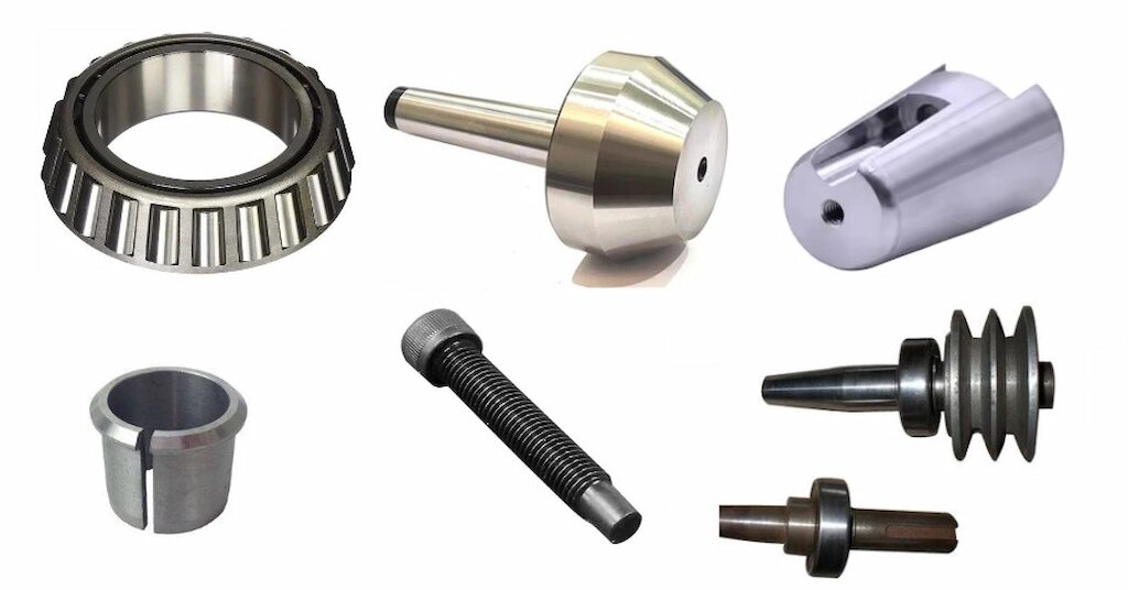
Machine Tool Components
Machine spindles, arbors, and tool holders often have precision tapers. Examples include Morse, Jacobs, and CAT tapers. These allow tools to seat firmly while still being easy to remove. The taper ensures accurate alignment between the tool and spindle, reducing vibration and improving machining accuracy.
Automotive and Aerospace Applications
In cars, trucks, and aircraft, tapered shafts and pins are used for connecting wheels, gears, and propellers. They transmit torque without slipping and can handle heavy loads. Tapered roller bearings, for example, support both radial and axial forces, making them ideal for high-speed or high-load situations.
Medical Devices and Tooling Systems
Surgical tools, dental handpieces, and orthopedic implants often use tapers for precise, secure connections. In tooling systems, quick-change holders and adapters rely on tapers to maintain alignment under repeated use. These designs allow fast assembly while ensuring stability and accuracy during operation.
Conclusion
Taper turning is a key lathe process used to create parts with changing diameters. It supports tight fits, smooth assemblies, and accurate alignment in many industries. There are several taper turning methods, and each fits different part types and accuracy needs. By choosing the right setup, cutting tools, and machining parameters, you can produce clean, accurate tapers with less rework.
Need help machining precision tapered parts? We support custom taper turning with fast lead times and tight tolerances. Contact us now to get a free quote for your next project.
Hey, I'm Kevin Lee

For the past 10 years, I’ve been immersed in various forms of sheet metal fabrication, sharing cool insights here from my experiences across diverse workshops.
Get in touch
Kevin Lee
I have over ten years of professional experience in sheet metal fabrication, specializing in laser cutting, bending, welding, and surface treatment techniques. As the Technical Director at Shengen, I am committed to solving complex manufacturing challenges and driving innovation and quality in each project.
Related Resource


Fingerprint Resistant Stainless Steel: How It Works,and How to Choose

