Many manufacturers struggle with complex parts that have changing shapes or curves. Standard turning methods often leave steps or rough surfaces. These issues can result in increased rework, longer lead times, and additional costs. Contour turning solves these problems. It allows you to create smooth, flowing shapes on a lathe with minimal manual finishing.
If you want to create parts with smooth curves or complex forms, contour turning can help you achieve this. See how it works and why it matters below.
What is Contour Turning?
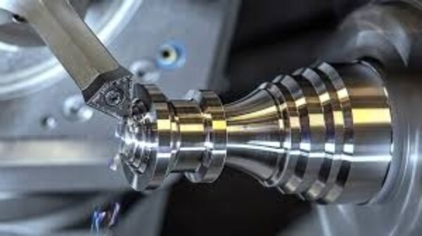
Contour turning is a lathe process in which the cutting tool moves in both the X and Z axes simultaneously. This multi-axis movement lets the tool follow a specific curved or angled path. The goal is to create smooth shapes, like arcs, rounded edges, or sloped profiles, on a rotating workpiece.
Unlike straight turning, where the tool makes simple cuts along a single axis, contour turning allows for more complex geometries. The shape of the final part depends on how the tool path is programmed.
This method is especially effective for parts that have changing diameters, such as camshafts, nozzles, or custom connectors. It’s most often done with CNC lathes for better control and accuracy.
How Does Contour Turning Work?
Contour turning follows a straightforward process to ensure accurate results. Here’s how it works in practice.
Step 1: Workpiece Preparation
Begin with a cylindrical raw material, often a round bar or forged blank, that is cut slightly longer than the final part length (typically with an extra 2–5 mm for facing and holding). Mount the workpiece securely in a three-jaw or four-jaw chuck, ensuring proper concentricity.
Clean the surface with a degreaser or alcohol-based solvent to remove oils or oxidation. For high-precision parts, it’s essential to check straightness using a dial indicator or V-blocks.
Step 2: Tool Selection and Setup
Select a cutting tool that matches the desired shape. The tool’s tip size, shape, and coating should match the material and the desired finish type. For example, use a tool with a 0.4 mm to 0.8 mm tip radius for general contour work.
Install the tool in the holder and set it on the machine centerline. Use a tool setter or align it manually. Keep the tool setup short and solid to reduce vibration.
Step 3: Program the CNC Lathe
Use CAM software or G-code to create the tool path. The program should control both X and Z movements to match the part’s shape. Set the cutting depth, feed rate, and spindle speed according to the material.
Here are some basic settings:
- Mild steel: 300–500 SFM (surface feet per minute)
- Stainless steel: 150–250 SFM
- Feed rate: 0.05–0.2 mm per revolution
Double-check the code before running it. Even small mistakes can cause tool crashes or scrap parts. If this job repeats, save the program for next time.
Step 4: Dry Run and Simulation (Optional but Recommended)
Run a simulation first. This can be done in the CAM software or on the CNC controller. It helps you visualize how the tool will move and identify any potential issues that may arise.
You can also do a dry run on the machine. In this step, the tool moves through the program without cutting the part. It lets you confirm the tool path, clearance, and turret movement. Always use slow speed and single-step mode during this check.
Step 5: Execute the Turning Operation
Once everything appears to be in order, start the machine and run the program. Watch the process. Ensure the tool cuts smoothly and that chips are clearing.
Look for signs of tool wear, vibration, or noise. Adjust the feed or speed if needed. After cutting, stop the machine and remove the part. Please measure the size and verify the shape to ensure it matches the drawing.
Types of Contour Turning Operations
Contour turning includes several methods. Each one is used based on the shape of the part and the area that needs to be cut. These methods help machinists create different types of profiles.
External Contour Turning
This method is used to shape the outside of a round part. The cutting tool moves along the outer surface to create curves, angles, or steps.
It’s commonly used for parts like shafts, sleeves, and casings. The process can form detailed shapes while maintaining a smooth surface.
Because the tool works on the outside, it’s easier to remove chips and keep the tool in the correct position. That’s why this method is widely used in many shops.
Internal Contour Turning
This method is used to cut shapes inside a hole or opening. The cutting tool moves through the inside and follows a curved or angled path.
It’s often used to create bores, grooves, or inner tapers. This type of work needs smaller tools and more careful planning.
Since the tool works inside the part, space is tight. Chips can build up quickly. A good setup and proper coolant flow are essential to keep things running smoothly.
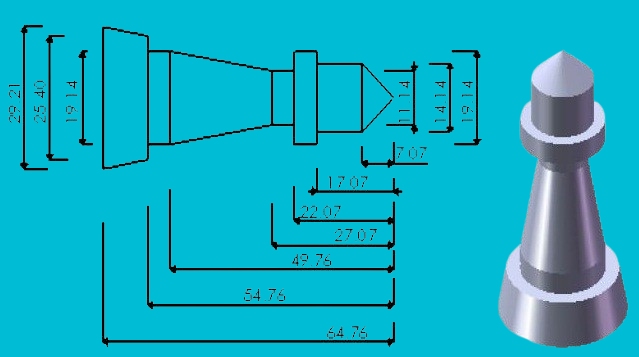
Complex Profile Turning
This method combines both internal and external cutting. The tool follows a path that includes several shapes, like curves, tapers, and step changes.
It’s often used for custom parts, such as connectors or shafts with multiple sections. The machine must follow a precise path to avoid crashes and maintain high accuracy.
This process relies on a well-designed CNC program and the appropriate tool selection. It may take longer to set up, but it saves time by finishing the part in one step.
Advantages of Contour Turning
Contour turning offers several benefits over basic turning methods. It allows shops to meet tighter specs, improve quality, and reduce production steps.
Complex Profile Machining
Contour turning enables the machining of parts with curves, tapers, and blended shapes. You don’t need multiple setups or custom fixtures. A single CNC program can cut detailed profiles in one operation. It gives more freedom in part design without raising costs.
Higher Precision and Consistency
CNC control allows exact tool movement along the X and Z axes. This ensures that every cut follows the same path. As a result, contour turning provides high part-to-part consistency. Tolerances stay tight even in long runs.
Better Surface Finish
Since the tool moves smoothly along the contour, there are fewer steps or tool marks. With proper feed rates, speeds, and tool geometry, contour turning produces clean, polished surfaces. This reduces or removes the need for extra polishing or grinding.
Time Efficiency for Complex Shapes
Instead of switching tools or repositioning the part, contour turning can create the entire shape in one pass. It combines roughing and finishing on the same path. This saves time, reduces handling, and accelerates production.
Applications of Contour Turning
Contour turning solves real manufacturing challenges across industries. Here’s where it delivers the most value:
Aerospace
Aerospace parts often have tapered sections, smooth transitions, and critical dimensions. Contour turning is used to machine turbine components, landing gear parts, and structural connectors. It enables manufacturers to meet strict tolerances while maintaining high surface quality.
Automotive
In the automotive sector, contour turning is used to make camshafts, steering rods, suspension pins, and valve parts. These parts need precise curves to function correctly. Contour turning reduces setup time and keeps each part uniform.
Medical Device Components
Medical tools and implants often feature rounded shapes and intricate, minor details. Parts like surgical handles, orthopedic implants, and dental components require smooth finishes and close tolerances. It helps meet the strict quality standards required in medical applications.
Mold and Die Production
Mold and die parts often require curved shapes and fine details, particularly for injection molding or die casting. Contour turning helps form these features directly on round inserts or pins. It reduces manual polishing and enables toolmakers to meet design specifications more quickly.
Best Practices for Effective Contour Turning
Achieving the best results in contour turning relies on careful planning and a well-structured setup. Here are a few best practices to keep your operation efficient and accurate.
Use the Right Tool Geometry
Choosing the correct tool geometry is critical for producing accurate profiles. The tool’s nose radius should match the detail level of the contour:
- Use a small nose radius (e.g., 0.2–0.4 mm) for sharp corners and tight radii.
- Use a larger nose radius (e.g., 0.8–1.2 mm) for smoother transitions and better surface finish.
Tool wear has a significant impact on surface quality and dimensional accuracy. Inspect inserts regularly under magnification. Look for signs of flank wear, chipping, or built-up edge (BUE). Replace worn inserts before reaching critical wear to avoid poor finishes or dimensional drift.
Optimize Cutting Parameters
Cutting speed (SFM), feed rate (mm/rev), and depth of cut (DOC) should be adjusted based on the workpiece material and tool type. For example:
- Stainless steel may require slower speeds (150–250 SFM) to control heat and wear.
- Aluminum allows for higher speeds (up to 600–1000 SFM) but requires sharp tools and good chip evacuation.
Use manufacturer-recommended values as a starting point. Fine-tune parameters based on part geometry, tool life, and surface finish results to optimize performance. Avoid excessive spindle speeds or feeds, which can cause tool chatter, vibration, or rapid insert failure.
Use Constant Surface Speed (CSS) mode in CNC programming whenever possible. This automatically adjusts spindle speed based on part diameter, ensuring consistent cutting conditions along curved surfaces.
Prioritize Proper Workholding
Secure and rigid workholding is essential to prevent deflection or vibration during turning. Use precision three-jaw chucks, collets, or custom fixtures that provide a firm grip without distorting the part.
Verify part alignment using a dial indicator. Total runout should remain below 0.01 mm for high-precision jobs. Inadequate clamping or off-center mounting can cause taper, ovality, or surface chatter.
For thin-walled or delicate parts, consider soft jaws or support from a live center or tailstock to reduce deformation under cutting pressure.
Conclusion
Contour turning is a CNC lathe process used to cut curved, angled, or complex profiles on round parts. It works by controlling the tool along two axes to follow a smooth, programmed path. This method enables machine parts to be produced with greater accuracy, cleaner finishes, and fewer steps.
Need help machining custom curved parts or complex profiles? Contact us today to get expert support and fast quotes for your next project.
Hey, I'm Kevin Lee

For the past 10 years, I’ve been immersed in various forms of sheet metal fabrication, sharing cool insights here from my experiences across diverse workshops.
Get in touch
Kevin Lee
I have over ten years of professional experience in sheet metal fabrication, specializing in laser cutting, bending, welding, and surface treatment techniques. As the Technical Director at Shengen, I am committed to solving complex manufacturing challenges and driving innovation and quality in each project.