Jeder Ingenieur kennt diesen Moment - wenn sich ein perfektes 3D-Modell einfach nicht entfalten will. Was auf dem Bildschirm toll aussieht, wird plötzlich zu einem echten Problem: Ecken reißen ein, Biegungen verziehen sich oder Löcher passen nicht zusammen. Das Frustrierende daran? Diese Probleme kommen nicht aus heiterem Himmel. Sie lassen sich vorhersehen - und verhindern.
In der Blechfertigung hängt die Grenze zwischen einer reibungslosen Produktion und einer kostspieligen Neukonstruktion oft von einigen wenigen Konstruktionsgewohnheiten ab. Studien zeigen, dass etwa 60% der Blechkonstruktionen Entfaltungsprobleme haben, die hätten vermieden werden können. Die meisten davon sind auf eine ungleichmäßige Dicke oder schlecht platzierte Löcher und Ausschnitte zurückzuführen.
Bei Shengen prüfen unsere Ingenieure jeden Monat Hunderte von 3D-Dateien. Wir sehen immer wieder dieselben Fehler - kleine Details im CAD, die bei der Fertigung zu großen Problemen führen. Damit Sie diese Probleme vermeiden können, finden Sie hier neun einfache Regeln, die das digitale Design mit der realen Produktion verbinden.
Vergleich von Blechkonstruktionsmethoden: Flach vs. Massiv
Bei der Erstellung von Blechteilen können Sie in zwei Richtungen vorgehen: Flat-First-Modellierung oder Solid-to-Sheet-Konvertierung.
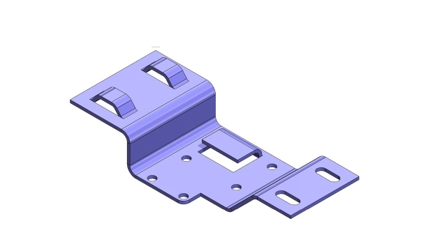
Bei der Flat-First-Modellierung wird mit einem flachen Layout begonnen und dann Biegungen hinzugefügt. Mit diesem Ansatz haben Sie eine bessere Kontrolle über Biegepositionen, Reliefs und den Materialfluss. Es ist perfekt für Teile wie Gehege, Plattenund Klammern wo Genauigkeit wirklich zählt.
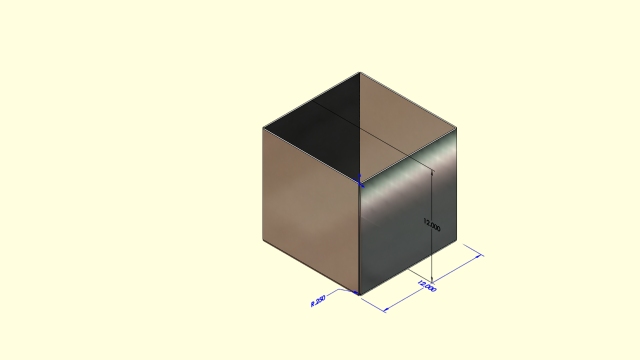
Bei der Konvertierung von Volumenkörpern in Bleche hingegen wird zunächst ein vollständiges 3D-Volumenmodell erstellt, das später in Bleche umgewandelt wird. Dies ist schneller für Konzeptentwürfe, aber riskanter beim Abflachen, insbesondere wenn das Modell unterschiedliche Dicken oder überlappende Bereiche hat.
Die richtige Methode hängt von Ihrem Projekt ab. Bei schnellen Prototypen spart es Zeit, mit einem Vollmaterial zu beginnen. Bei großen Produktionsserien oder Baugruppen, die enge Toleranzen erfordern, reduziert ein flacher Start die Fehlerquote und sorgt dafür, dass Ihre Teile von Charge zu Charge gleich bleiben.
Regel 1: Beginnen Sie mit den richtigen CAD-Blechwerkzeugen
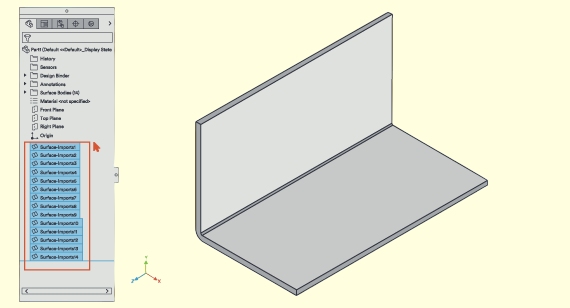
Verwenden Sie von Anfang an die in Ihre CAD-Software integrierten Blechbearbeitungswerkzeuge. Befehle wie "In Blech konvertieren", "Abflachen" und "Auffalten" helfen Ihrem System zu verstehen, wie sich Biegungen, Flansche und Reliefs in der Realität verhalten.
Wenn Sie mit diesen Werkzeugen entwerfen, behält Ihr Modell eine gleichmäßige Dicke, genaue Biegeformen und richtige Reliefs. Wenn Sie sie auslassen, können Abwicklungsfehler auftreten - wie unebene Wände, überlappende Flächen oder misslungene flache Muster.
Prüfen Sie vor dem Modellieren, ob die Materialstärke stimmt, Biegeradiusund K-Faktor den Standards Ihres Unternehmens entsprechen. Wenn Sie diese Details frühzeitig klären, können Sie Nacharbeiten vermeiden und später sowohl Zeit als auch Kosten sparen.
Regel 2: Gleichmäßige Materialdicke beibehalten
Eine gleichbleibende Dicke ist der Schlüssel zu einem zuverlässigen Blechdesign. Sobald die Wandstärke variiert, wird Ihr Flachmuster schwer vorhersehbar. Biegungen werden ungleichmäßig gedehnt, Löcher fluchten nicht mehr, und die fertigen Teile verlieren an Genauigkeit.
Verwenden Sie immer die gleiche Dicke für das gesamte Teil. Bei rostfreiem Stahl ist ein Bereich von 0,8-2,0 mm gut geeignet. Für Aluminium sind 1,0-3,0 mm typisch. Wenn Sie mehr Festigkeit benötigen, fügen Sie Rippen oder Stützklammern hinzu, anstatt die Wandstärke zu erhöhen.
Eine einheitliche Dicke macht das Biegen vorhersehbarer und reduziert die Rüstzeit in der Werkstatt. Außerdem kann so sichergestellt werden, dass jedes produzierte Teil dem ursprünglichen Entwurf entspricht.
Regel 3: Wenden Sie den korrekten Biegeradius und K-Faktor an
Nachdem Sie die Dicke eingestellt haben, kontrollieren Sie, wie sich das Blech biegt. Der Biegeradius hat Einfluss darauf, wie das Material fließt. Wenn er zu eng ist, kann das Metall reißen. Ist er zu weit, wird die Biegeform undeutlich. Ein sicherer Ausgangspunkt ist es, den inneren Biegeradius gleich der Materialstärke zu halten.
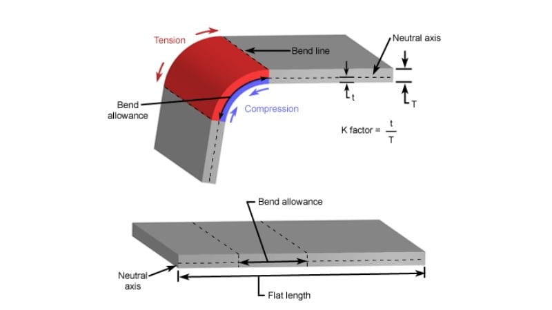
Der K-Faktor gibt an, wie sehr sich das Metall beim Biegen dehnt. Die meisten Materialien liegen zwischen 0,3 und 0,5. Weichere Metalle wie Aluminium funktionieren in der Regel am besten bei 0,33, während stärkere Metalle wie rostfreier Stahl bei 0,45 gut funktionieren.
Mit dem richtigen K-Faktor und Biegeradius kann Ihr CAD-System genaue flache Längen berechnen. Dadurch wird sichergestellt, dass das endgültige Formteil perfekt mit dem Entwurf übereinstimmt, sobald es die Abkantpresse verlässt.
Regel 4: Verwenden Sie die richtige Biegeentlastung und Eckentlastung
Jede Biegung braucht ein wenig Platz, um sich zu bewegen. Wenn Metall gebogen wird, wird die Innenkante zusammengedrückt, während die Außenseite gedehnt wird. Ohne ausreichende Entlastung kann diese Spannung zu Rissen, Ausbeulungen oder sichtbaren Spuren am fertigen Teil führen.
Fügen Sie an den Stellen, an denen Flansche auf Biegungen treffen, schmale Entlastungsschlitze ein. Eine gute Regel ist, dass die Schlitzbreite mindestens der Materialstärke entspricht. Verwenden Sie für Ecken kleine rechteckige oder V-förmige Aussparungen, um ein Ausreißen zu verhindern.
Das richtige Reliefdesign hilft auch bei Oberflächenveredelung. Farbe oder Pulverbeschichtung fließt gleichmäßiger um die Ecken, anstatt sich in engen Bereichen zu stauen. Schon ein paar Millimeter Spielraum bei der Gestaltung können später stundenlanges Schleifen oder Ausbessern ersparen.
Regel 5: Halten Sie Merkmale von Knicklinien fern
Selbst ein einziges Loch, das zu nahe an einer Biegung angebracht ist, kann Probleme verursachen. Wenn sich das Metall verformt, können sich nahe gelegene Merkmale dehnen, verformen oder Druckstellen aufweisen.
Halten Sie Löcher, Schlitze oder geprägte Formen mindestens das Vierfache der Materialdicke von jeder Knicklinie entfernt. Wenn Ihr Blech zum Beispiel 1 mm dick ist, müssen die Merkmale mindestens 4 mm von der Falz entfernt sein.
Dieses kleine Detail schützt sowohl Ihr Teil als auch die Werkzeuge der Abkantpresse. Ein falsch platziertes Loch kann eine Fehlbiegung verursachen oder sogar eine Matrize zerkratzen, was das gesamte Los beeinträchtigt. Die Einhaltung dieses Abstands trägt zu einer reibungslosen Produktion und weniger Ausschuss bei.
Regel 6: Frühzeitige Planung der Herstellbarkeit
Bei einem großartigen Design geht es nicht nur um die Form, sondern auch darum, wie gut es hergestellt werden kann. Jede Maschine in der Werkstatt hat ihre Grenzen, z. B. bei der Biegelänge, dem Werkzeugabstand und der Ausladung.
Bevor Sie Ihr Design festschreiben, sollten Sie sich mit Ihrem Fertigungsteam abstimmen. Vergewissern Sie sich, dass Ihr größter Flansch für die Kapazität der Abkantpresse geeignet ist, dass das von Ihnen gewählte Material zu den verfügbaren Werkzeugen passt und dass kleine interne Merkmale tatsächlich geschnitten werden können.
Selbst ein kleiner Fehler - wie ein nur 10 mm zu langer Flansch - kann die Produktion stoppen. Wer von Anfang an an die Herstellbarkeit denkt, spart Zeit, reduziert den Ausschuss und vermeidet Umgestaltungen in letzter Minute. Die Optimierung Ihres flachen Layouts kann sogar den Materialverbrauch um einige Prozent senken - eine Einsparung, die sich direkt auf Ihr nächstes Angebot auswirkt.
Regel 7: Validieren Sie das flache Muster vor der Produktion
Sobald Ihr Entwurf fertig ist, sollten Sie das flache Muster immer überprüfen, bevor Sie es an die Produktion schicken. Verwenden Sie den Befehl "Abflachen" oder "Entfalten" Ihres CAD-Systems, um zu sehen, wie das Teil nach dem Auslegen aussehen wird. Wenn sich das flache Muster überlappt, fehlende Kanten aufweist oder sich nicht auffalten lässt, beheben Sie diese Probleme, bevor Sie die Datei freigeben.
Exportieren Sie das flache Layout als DXF- oder STEP-Datei und vergleichen Sie es mit Ihrem Schneidplan. Vergewissern Sie sich, dass die Löcher übereinstimmen, die Biegelinien eindeutig sind und die Kanten die richtigen Abstände haben. Selbst eine kleine Abweichung von 1 mm kann später bei der Montage ernsthafte Probleme verursachen.
Dieser Schritt dauert nur ein paar Minuten, kann aber Materialverschwendung, Produktionsverzögerungen und teure Nacharbeiten verhindern, sobald das Teil in der Werkstatt angekommen ist.
Regel 8: Berücksichtigung des Materialverhaltens beim Biegen
Metall lässt sich nicht jedes Mal perfekt biegen. Jedes Material dehnt und staucht sich und federt nach dem Umformen auf seine eigene Weise zurück. Wird dies nicht beachtet, kann es zu Biegungen kommen, die leicht schief sind, oder zu Teilen, die nicht wie geplant passen.
Weiche Werkstoffe wie Aluminium federn in der Regel um 1-3° stärker zurück als rostfreier Stahl. Um dies auszugleichen, können Sie den Biegeradius verringern oder Aluminiumteile beim Formen leicht überbiegen.
Eine schnelle Testbiegung hilft Ihnen, die richtigen Einstellungen zu bestätigen. Mit der Zeit hilft Ihnen die Aufzeichnung Ihrer realen Biegedaten, schneller zu konstruieren und bei zukünftigen Projekten genauere Ergebnisse zu erzielen.
Regel 9: Nachgelagerte Prozesse berücksichtigen
Selbst ein perfektes flaches Muster muss nach dem Formen noch bearbeitet werden. SchweißenBeschichtung, und Montage wirken sich alle auf die Passform und das Aussehen Ihres Teils aus.
Lassen Sie zusätzlichen Freiraum für Schweißnähte, Nieten oder Befestigungsmaterial. Vermeiden Sie scharfe Ecken, an denen sich Pulver oder Farbe ablagern könnte. Beschichtungen können 0,05-0,15 mm pro Seite hinzufügen, was den Zusammenbau eines engen Gehäuses erschweren kann.
Wenn das Teil geschweißt werden muss, fügen Sie Entlastungskerben oder Befestigungslöcher hinzu, um die Wärmeverformung zu kontrollieren. Durch frühzeitiges Nachdenken über diese Endbearbeitungs- und Montageschritte wird sichergestellt, dass Ihr Teil richtig aussieht, richtig passt und nach der Fertigstellung die beabsichtigte Leistung erbringt.
Schlussfolgerung
Bei der Konstruktion von Blechteilen geht es nicht nur darum, Formen zu entwerfen - es geht darum, Geometrien zu schaffen, die tatsächlich hergestellt werden können. Jede Regel in diesem Leitfaden überbrückt die Lücke zwischen Design und realer Produktion.
Beginnen Sie mit den richtigen CAD-Werkzeugen. Halten Sie die Materialstärke gleichmäßig. Fügen Sie geeignete Reliefs hinzu. Geben Sie Features genügend Abstand zu Biegungen. Überprüfen Sie Ihr flaches Muster. Und denken Sie immer daran, wie das Teil geschweißt, beschichtet und montiert werden soll. Diese einfachen Gewohnheiten können einen komplexen Fertigungsprozess in einen reibungslosen und vorhersehbaren Arbeitsablauf verwandeln.
Bei Shengen wenden unsere Ingenieure diese Prinzipien jeden Tag an. Wir helfen unseren Kunden, 3D-Konzepte in präzise, kosteneffiziente und produktionsreife Blechteile umzusetzen.
Bevor Sie Ihre nächste RFQ versenden, Laden Sie Ihre CAD-Datei für eine kostenlose DFM-Prüfung hoch. Unser Ingenieurteam analysiert Ihren Entwurf, weist auf mögliche Risiken hin und schlägt kleine Verbesserungen vor, die Kosten und Vorlaufzeit reduzieren - und das alles innerhalb von 24 Stunden.
FAQ
Was passiert, wenn ein 3D-Entwurf nicht entfaltet werden kann?
In der Regel bedeutet dies, dass das Modell gegen eine oder mehrere Blechregeln verstößt - uneinheitliche Dicke, fehlende Reliefs oder überlappende Flansche. Fangen Sie nicht von vorne an. Vereinfachen Sie ein Feature nach dem anderen, überprüfen Sie die Wandstärke und wenden Sie den Befehl zur Blechkonvertierung erneut an. In den meisten Fällen handelt es sich nur um ein kleines Geometrieproblem, das schnell behoben werden kann.
Wie wähle ich den richtigen K-Faktor für mein Material?
Verwenden Sie einen Anfangswert von 0,33 für Aluminium und 0,4-0,45 für unlegierten oder rostfreien Stahl. Führen Sie eine kurze Testbiegung mit den aktuellen Werkzeugen Ihres Unternehmens durch, um diesen Wert anzupassen. Der richtige K-Faktor stellt sicher, dass die Abmessungen Ihres flachen Musters genau mit dem geformten Teil übereinstimmen.
Wie lässt sich ein flaches Muster vor der Herstellung am besten überprüfen?
Verkleinern Sie Ihr Modell immer in CAD und exportieren Sie eine DXF-Datei. Vergleichen Sie diese mit Ihrem Zuschnitt, um zu prüfen, ob es Überlappungen, Lücken oder fehlende Kanten gibt. Selbst ein Unterschied von 1 mm kann nach dem Formen zu großen Problemen bei der Montage führen.
Wie unterscheidet sich die Rückfederung zwischen Aluminium und rostfreiem Stahl?
Aluminium hat eine höhere Elastizität, so dass es etwa 1-3° mehr zurückfedert als Edelstahl. Um dies auszugleichen, können Sie es leicht überbiegen oder einen kleineren Biegeradius verwenden. Nichtrostender Stahl behält seinen geformten Winkel aufgrund seiner Steifigkeit konsequenter bei.
Hey, ich bin Kevin Lee

In den letzten 10 Jahren bin ich in verschiedene Formen der Blechbearbeitung eingetaucht und teile hier coole Erkenntnisse aus meinen Erfahrungen in verschiedenen Werkstätten.
Kontakt aufnehmen
Kevin Lee
Ich verfüge über mehr als zehn Jahre Berufserfahrung in der Blechverarbeitung und bin auf Laserschneiden, Biegen, Schweißen und Oberflächenbehandlungstechniken spezialisiert. Als Technischer Direktor bei Shengen bin ich bestrebt, komplexe Fertigungsherausforderungen zu lösen und Innovation und Qualität in jedem Projekt voranzutreiben.
Verwandte Ressource

Fingerabdruckresistenter Edelstahl: Funktionsweise und Auswahl

OEM vs. Auftragsfertigung: Wie Sie das richtige Modell für Ihr Projekt wählen

