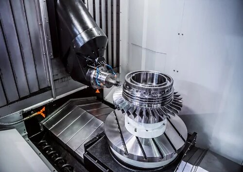
يتضمن التصميم للتصنيع الآلي باستخدام الحاسب الآلي فهم إمكانيات وقيود العملية. وسواء كنت تعمل على نماذج أولية أو تخطط للإنتاج بكميات كبيرة، يمكن أن يؤدي سوء تصميم القِطع إلى زيادة التكاليف والتأخير وإهدار الموارد. لتجنب هذه المشكلات، فإن تطبيق مبادئ التصميم العملية من البداية هو المفتاح لتحقيق أفضل النتائج.
لتصميم الماكينات بنظام التحكم الرقمي بنجاح، ضع في اعتبارك اختيار المواد، والهندسة، والتفاوتات المسموح بها، واتجاه الجزء. حافظ على بساطة التصميمات، وركز على سهولة التصنيع، وقلل من التعقيدات غير الضرورية. كما يجب مراعاة عملية التصنيع الآلي والأدوات وعدد القِطع المنتجة لتحسين الكفاءة والفعالية من حيث التكلفة.
مع وضع هذه الأساسيات في الاعتبار، من السهل أن ترى كيف يمكن لنهج التصميم الصحيح أن يحسن بشكل كبير من أوقات الإنتاج، ويقلل من الأخطاء، ويقلل من التكاليف. دعونا نلقي نظرة عن كثب على المبادئ الأساسية وراء التصميم الفعال للتصنيع الآلي باستخدام الحاسب الآلي.
مبادئ التصميم الأساسية للتصنيع الآلي باستخدام الحاسب الآلي
يتطلب تصميم القِطع للتشغيل الآلي باستخدام الحاسب الآلي تخطيطًا دقيقًا ومراعاة عدة عوامل رئيسية. دعنا نستكشف المبادئ الأساسية التي يجب عليك اتباعها لتحقيق نتائج ناجحة.
تصميم من أجل التصنيع
يعني التصميم من أجل قابلية التصنيع (DFM) إنشاء أجزاء سهلة وفعالة للإنتاج. وهذا يقلل من التكاليف ويسرّع الإنتاج ويقلل من الأخطاء.
- تبسيط الهندسة: تجنب التعقيد غير الضروري. استخدم الخطوط المستقيمة والمنحنيات البسيطة والأشكال القياسية كلما أمكن ذلك.
- تقليل خطوات التصنيع: تصميم أجزاء تتطلب إعدادات وتغييرات أدوات أقل. سيوفر ذلك الوقت ويقلل من فرصة حدوث أخطاء.
- توحيد الميزات: استخدم أحجام الفتحات القياسية وأنواع الخيوط اللولبية وأحجام أدوات التثبيت لتبسيط التصنيع الآلي و حَشد.
التفاوتات والملاءمة: الإرشادات الأساسية
تحدد التفاوتات المسموح بها مقدار التفاوتات المسموح بها التي يمكن أن تختلف أبعاد الجزء مع الاستمرار في العمل بشكل صحيح. تؤدي التفاوتات المسموح بها الضيقة إلى زيادة التكاليف، لذا لا تستخدمها إلا عند الضرورة.
- الميزات الحرجة مقابل الميزات غير الحرجة: تطبيق تفاوتات تحمل ضيقة على الميزات التي تؤثر على وظيفة الجزء، مثل أسطح التزاوج. استخدم التفاوتات القياسية للمناطق غير الحرجة.
- فهم متطلبات الملاءمة: تسمح تركيبات الخلوص للأجزاء بالتحرك بحرية، في حين أن نوبات التداخل إنشاء رابطة محكمة. اختر الملاءمة المناسبة لاستخدامك.
- التواصل بوضوح: حدِّد التفاوتات المسموح بها بوضوح على رسوماتك لتجنب الارتباك أثناء الإنتاج.
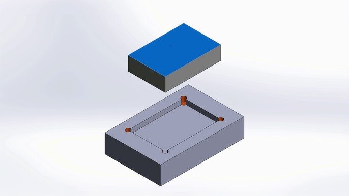
النظر في الوصول إلى الأدوات وحركتها
تستخدم ماكينات CNC أدوات القطع لإزالة المواد. يجب أن يسمح تصميمك لهذه الأدوات بالوصول إلى جميع مناطق الجزء دون مشاكل.
- تجنب التجاويف العميقة والضيقة: قد يكون من الصعب تشغيلها آليًا وقد تتطلب أدوات متخصصة.
- استخدام أنصاف الأقطار في الزوايا الداخلية: يصعب تشغيل الزوايا الحادة آليًا. استخدم أنصاف أقطار للسماح للأدوات القياسية بالعمل بفعالية.
- ضمان الخلوص الكافي: اترك مساحة كافية حول الميزات لكي تتحرك الأداة بحرية دون تصادمات.
قواعد تصميم CNC الأساسية
يتطلب تصميم الماكينات بنظام التحكم الرقمي الاهتمام بالتفاصيل والالتزام بقواعد محددة. تساعد هذه الإرشادات في ضمان سهولة تصنيع القِطع الخاصة بك آليًا وفعالية التكلفة والجودة العالية. دعنا نتعمق في الأساسيات.
اختيار المواد
اختيار المادة المناسبة هو أول قرار حاسم بالنسبة لك. فهو يؤثر على كل شيء بدءًا من قابلية التشغيل الآلي وحتى أداء الجزء النهائي.
النظر في قابلية التشغيل الآلي
تختلف المواد اختلافًا كبيرًا في مدى سهولة تشكيلها آليًا. سبائك الألومنيوم مثل 6061 ممتازة للعمل بنظام التحكم الرقمي لأنها تقطع بسرعة وتنتج تشطيبات سطحية جيدة. يستغرق الفولاذ وقتًا أطول وتآكل الأدوات. تحتاج المواد الغريبة مثل التيتانيوم أو الإنكونيل إلى أدوات خاصة وسرعات أبطأ.
يرتبط عمر الأداة ارتباطًا مباشرًا بصلابة المواد. فالمواد اللينة مثل النحاس الأصفر أو الألومنيوم أسهل على أدوات القطع، بينما المواد الأكثر صلابة تسبب تآكلًا أسرع للأدوات وقد تحتاج إلى طلاء خاص.
خصائص المواد
بالإضافة إلى قابلية التصنيع الآلي، ضع في اعتبارك كيفية أداء المادة في تطبيقك. فكّر في:
- متطلبات القوة
- قيود الوزن
- الخواص الحرارية
- مقاومة كيميائية
- قيود التكلفة
سمك الحائط
تؤثر سماكة الجدار على كل من جدوى التشغيل الآلي وقوة الجزء. إن الحصول على هذا الأمر بشكل صحيح يمنع الالتواء والفشل.
الحد الأدنى من المتطلبات
المواد المختلفة لها متطلبات مختلفة للحد الأدنى لسُمك الجدار. بالنسبة للألومنيوم، ابقَ فوق 0.8 مم. يجب أن تحافظ الأجزاء الفولاذية على سمك 1 مم على الأقل. يمكن أن تهتز الجدران الأقل سمكًا أثناء التصنيع الآلي، مما يتسبب في سوء تشطيب السطح أو أخطاء في الأبعاد.
كلما كان الجيب أو التجويف أعمق، يجب أن تكون الجدران المحيطة أكثر سمكًا. والقاعدة الجيدة هي أن سمك الجدار يجب أن يكون على الأقل 10% من ارتفاع الجدار لمنع الانثناء أثناء التشغيل الآلي.
تصميم موحد
حافظ على ثبات سُمك الجدار في جميع أنحاء تصميمك. يتسبب اختلاف السُمك في حدوث تبريد غير متساوٍ ويمكن أن يؤدي إلى التواء أو إجهاد داخلي. عند الحاجة إلى تغييرات في السماكة، استخدم انتقالات تدريجية بدلاً من التغييرات المفاجئة.
تعمل الجدران الموحدة أيضًا على تبسيط اختيار الأداة وتقليل عدد العمليات المطلوبة، مما يقلل من تكاليف الإنتاج.
تصميم الزاوية
يؤثر تصميم الزاوية بشكل كبير على صعوبة التصنيع وقوة الجزء. التفاصيل الصغيرة هنا تحدث اختلافات كبيرة.
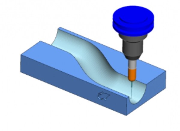
نصف قطر الزاوية الداخلية
قم دائمًا بتضمين نصف قطر داخلي على الزوايا الداخلية. تستخدم ماكينات التفريز باستخدام الحاسب الآلي أدوات قطع دائرية لا يمكنها إنشاء زوايا داخلية مثالية بزاوية 90 درجة. يجب أن يتطابق الحد الأدنى لنصف القطر الداخلي مع نصف قطر الأداة المستخدم في القطع النهائي.
تعمل أنصاف الأقطار الداخلية الأكبر على تقليل تركيزات الإجهاد وإطالة عمر الأداة. لتبسيط الإنتاج، استخدم أنصاف أقطار تتطابق مع أحجام ماكينة التفريز الطرفية القياسية (على سبيل المثال، 1/8 بوصة، 1/4 بوصة).
الزوايا الخارجية
يمكن تشكيل الزوايا الخارجية إلى نصف قطر قريب من الصفر، ولكن إضافة أنصاف أقطار صغيرة لها مزايا. تتشقق الزوايا الحادة بسهولة وتخلق نقاط إجهاد. يعمل نصف القطر الصغير (0.5 مم أو أكثر) على زيادة قوة الزوايا بشكل كبير مع الحد الأدنى من التأثير البصري.
تقلل أنصاف الأقطار الخارجية أيضًا من وقت التشغيل الآلي وتحسّن من تشطيب السطح من خلال السماح بحركة الأداة المستمرة بدلاً من التغييرات السريعة في الاتجاه.
الثقوب والثقوب
التصميم السليم للثقب يوفر الوقت ويحسن الجودة. يمكن أن يكون للتغييرات الصغيرة هنا تأثيرات كبيرة على تكاليف الإنتاج.
عمق الحفرة
عند الإمكان، قلل عمق الثقب إلى ما لا يزيد عن أربعة أضعاف قطر الثقب. فالثقوب العميقة أصعب في التشغيل الآلي وتتطلب أدوات خاصة وتزيد من خطر كسر الأدوات.
ضع في اعتبارك استخدام عملية مكبس الحفر قبل التصنيع الآلي باستخدام الحاسب الآلي أو التصميم لإعدادات تصنيع آلي متعددة للثقوب العميقة.
المقاسات القياسية
استخدم مقاسات الحفر القياسية كلما أمكن. تتطلب الثقوب ذات القطر المخصص عمليات الثقب النهائي، والتي تستغرق وقتًا أطول من الحفر القياسي. تعمل المقاسات الكسرية الشائعة (1/8″، 1/4″، إلخ) أو المقاسات المترية (3 مم، 5 مم، إلخ) على تبسيط عملية التصنيع.
بالنسبة للثقوب الدقيقة، قم بتصميم ثقوب صغيرة الحجم قليلاً متبوعة بالتوسيع إلى البعد النهائي. يوفر هذا النهج تحكمًا أفضل في التفاوت.
الثقوب الملولبة
توفير عمق كافٍ لتعشيق اللولب بشكل مناسب في الثقوب الملولبة. القاعدة الجيدة هي 1.5 × قطر اللولبة للصلب و2 × للألومنيوم أو البلاستيك.
تجنب تصميم اللوالب التي تصل إلى أسفل الثقوب العمياء. اترك مساحة لخلوص البُرادة ونفاد الأداة. أضف 1/2 قطر لولبة إضافية على الأقل من عمق اللولبة غير الملولبة في الأسفل.
التسامح
توازن التفاوتات المناسبة بين احتياجات الدقة وتكاليف التصنيع. الإحكام ليس دائمًا أفضل.
التفاوتات الافتراضية
يوفر التصنيع الآلي باستخدام الحاسب الآلي القياسي عادةً تفاوتات تفاوتات تفاوت قياسية تبلغ ± 0.125 مم (± 0.005″) دون عناية خاصة. تزيد التفاوتات الأكثر إحكامًا من التكاليف بشكل كبير. حدد فقط التفاوتات المسموح بها المشددة على السمات الحرجة وليس الجزء بأكمله.
بالنسبة لأجزاء التزاوج، ركز متطلبات التفاوت على الأسطح البينية بدلاً من المكونات بأكملها. يعمل هذا النهج المستهدف على تحسين الملاءمة مع الحفاظ على التكاليف معقولة.
صقل الأسطح
تؤثر متطلبات تشطيب السطح على استراتيجية التصنيع الآلي والوقت. تُنتج عمليات التصنيع باستخدام الحاسب الآلي القياسية تشطيبات سطحية قياسية تبلغ 3.2 ميكرومتر Ra أو أفضل. تتطلب التشطيبات الأكثر نعومة عمليات تشطيب إضافية وزيادة التكلفة.
حدد تشطيب السطح فقط عند الحاجة. قد تحتاج الأسطح الوظيفية إلى تشطيبات دقيقة، بينما يمكن استخدام التشطيبات القياسية في المناطق الهيكلية غير المرئية لتقليل التكلفة.
أنواع عمليات التصنيع باستخدام الحاسب الآلي وانعكاساتها التصميمية
عمليات التصنيع باستخدام الحاسب الآلي المختلفة لها متطلبات وقيود فريدة من نوعها. يساعدك فهم هذه المتطلبات والقيود على تصميم القِطع التي يتم تحسينها لكل طريقة. دعنا نستكشف اعتبارات التصميم الرئيسية للطحن والخراطة والحفر.
الطحن: اعتبارات التصميم لماكينات الطحن
طحن تستخدم أدوات القطع الدوارة لإزالة المواد من قطعة العمل. وهي مثالية لإنشاء أشكال وميزات معقدة.
- تجنب البروزات المتراكمة: تتطلب الأجزاء المتراكبة أدوات وإعدادات متخصصة. تصميم القِطع ذات الحد الأدنى من التراكبات لتبسيط التصنيع الآلي.
- استخدام مقاسات الأدوات القياسية: تصميم ميزات مثل الجيوب والفتحات لتتناسب مع أحجام الأدوات القياسية. وهذا يقلل من وقت التصنيع والتكاليف.
- النظر في الوصول إلى الأدوات: تأكد من قدرة أداة التفريز على الوصول إلى جميع مناطق الجزء. تجنب التجاويف العميقة والضيقة التي يصعب تشغيلها آليًا.
الخراطة: إرشادات التصميم الأساسية لعمليات الدوران
تحول تقوم بتدوير قطعة العمل بينما تقوم أداة القطع بإزالة المواد. إنها الأفضل لإنشاء أجزاء أسطوانية.
- التماثل هو المفتاح: يعمل الخراطة بشكل أفضل مع التصاميم المتماثلة. تجنب السمات غير المتماثلة التي تعقد العملية.
- التقليل من الجدران الرقيقة: يمكن للجدران الرقيقة أن تهتز أو تتشوه أثناء الدوران. تصميم جدران أكثر سمكاً لتحقيق الثبات.
- استخدام الشرائح والشرائح: إضافة الشطب أو الشرائح إلى الحواف لتقليل الزوايا الحادة وتحسين قوة الجزء.
الحفر عوامل التصميم للحفر
حفر إنشاء ثقوب في قطعة عمل باستخدام مثقاب دوّار. إنها عملية قياسية في التصنيع الآلي باستخدام الحاسب الآلي.
- عمق الفتحة وقطرها: حافظ على أعماق الحفرة معقولة. من الأفضل أن تكون نسبة العمق إلى القطر 4:1 أو أقل. تتطلب الثقوب الأعمق أدوات خاصة.
- تجنب الثقوب العمياء: الثقوب العرضية أكثر سهولة في الحفر من الثقوب العمياء. لا تستخدم الثقوب العمياء إلا عند الضرورة.
- توحيد مقاسات الفتحات: استخدم أحجام لقم الثقب القياسية لتقليل تغيير الأدوات وتوفير الوقت.
أفضل الممارسات للتصميم باستخدام الحاسب الآلي الرقمي
خيارات التصميم المدروسة تجعل التصنيع الآلي أسرع وأرخص وأكثر دقة. يمكن أن يؤدي اتباع أفضل الممارسات هذه إلى تحسين تصميماتك للحصول على نتائج أفضل.
تحسين توجيه الجزء وإعداده على النحو الأمثل
تؤثر كيفية توجيه الجزء أثناء التصنيع الآلي على كل من الجودة والكفاءة. يقلل التوجيه السليم من عمليات الإعداد ويقلل من الأخطاء.
- تصغير الإعدادات: تصميم القِطع التي يمكن تشكيلها آليًا بأقل عدد ممكن من الإعدادات. وهذا يوفر الوقت ويقلل من مشاكل المحاذاة.
- التموضع المستقر: تأكد من إمكانية تثبيت الجزء بإحكام. تجنب التصاميم ذات التوزيع غير المتساوي للوزن أو السمات الهشة التي يمكن أن تنكسر أثناء التشغيل الآلي.
- ميزات يسهل الوصول إليها: قم بتوجيه الجزء بحيث تكون الميزات الحرجة سهلة التشغيل الآلي. على سبيل المثال، يجب وضع الثقوب أو الفتحات في الجزء العلوي أو الجانبي لتحسين الوصول إلى الأداة.
التصميم مع وضع الوصول إلى الأدوات في الاعتبار
تستخدم ماكينات التحكم الرقمي باستخدام الحاسب الآلي أدوات القطع لتشكيل الأجزاء. يجب أن يسمح تصميمك لهذه الأدوات بالوصول إلى جميع المناطق دون مشاكل.
- تجنب الميزات العميقة والضيقة: الجيوب العميقة أو الفتحات الضيقة يمكن أن يكون من الصعب تشغيلها آليًا. استخدم ميزات أوسع وأقل عمقاً عندما يكون ذلك ممكناً.
- استخدام أنصاف الأقطار في الزوايا: يصعب تشغيل الزوايا الداخلية الحادة في الماكينة. أضف أنصاف أقطار لمطابقة حجم الأداة وتحسين عمر الأداة.
- ضمان التخليص: اترك مساحة كافية حول الميزات لكي تتحرك الأداة بحرية. هذا يمنع التصادمات ويضمن سلاسة التصنيع الآلي.
استخدام الأجزاء والتصاميم الموحدة
يبسّط التوحيد القياسي الإنتاج ويقلل التكاليف ويسرّع من المهل الزمنية.
- الميزات القياسية: استخدم أحجام الثقوب وأنواع الخيوط اللولبية وأحجام أدوات التثبيت الشائعة. وهذا يقلل من الحاجة إلى أدوات وإعدادات مخصصة.
- التصاميم المعيارية: تقسيم الأجزاء المعقدة إلى مكونات أبسط وموحدة. وهذا يجعل التصنيع الآلي أسهل ويسمح بإجراء إصلاحات أو عمليات استبدال أكثر بساطة.
- إعادة استخدام التصاميم: عند الإمكان، أعد استخدام التصميمات أو القوالب الموجودة. وهذا يوفر الوقت ويضمن الاتساق بين المشاريع.
خاتمة
يتطلب تصميم الماكينات بنظام التحكم الرقمي توازنًا بين الإبداع والتطبيق العملي. من خلال التركيز على البساطة، واختيار المواد، والتفاوتات المسموح بها، والوصول إلى الأدوات، يمكنك إنشاء قِطَع فعّالة وفعّالة من حيث التكلفة وعالية الجودة.
في Shengen، نحن متخصصون في تحويل تصميماتك إلى قطع عالية الجودة ومشكّلة بدقة. وسواء كنت بحاجة إلى نماذج أولية سريعة أو إنتاج ضخم، فإن فريقنا هنا لمساعدتك. اتصل بنا اليوم لمناقشة مشروعك والحصول على عرض أسعار مجاني.
مهلا، أنا كيفن لي

على مدى السنوات العشر الماضية، كنت منغمسًا في أشكال مختلفة من تصنيع الصفائح المعدنية، وشاركت رؤى رائعة هنا من تجاربي عبر ورش العمل المتنوعة.
ابقى على تواصل
كيفن لي
لدي أكثر من عشر سنوات من الخبرة المهنية في تصنيع الصفائح المعدنية، وتخصصت في القطع بالليزر، والثني، واللحام، وتقنيات معالجة الأسطح. كمدير فني في شنغن، أنا ملتزم بحل تحديات التصنيع المعقدة ودفع الابتكار والجودة في كل مشروع.
الموارد ذات الصلة

الفولاذ المقاوم للصدأ المقاوم لبصمات الأصابع: كيف يعمل، وكيف تختار


