Если отверстия, сгибы или тиснения расположены слишком близко друг к другу, качество формовки быстро падает. Металл не может равномерно растягиваться, что приводит к появлению трещин, морщин или искажению формы. Эти проблемы увеличивают количество брака, быстрее изнашивают инструменты и замедляют производство. Чаще всего причина кроется в плохом расположении элементов на этапе проектирования.
Надежная формовка начинается с правильного расстояния между элементами. Соблюдение достаточного расстояния между элементами позволяет металлу свободно течь. Это снижает напряжение и помогает поддерживать постоянную геометрию детали. Хорошее расстояние между элементами также защищает оснастку, улучшает повторяемость и снижает производственные затраты.
Проектирование с правильным расстоянием между элементами делает разницу между гладким и рискованным процессом. Давайте рассмотрим, как работает расстояние и почему оно имеет значение при проектировании любого листового металла.

Основы приближения элементов при проектировании листового металла
Близость элементов означает расстояние между такими элементами, как отверстия, изгибы, тиснения или вырезы на детали из листового металла. Это расстояние напрямую влияет на поведение материала во время формовки. Если элементы расположены слишком близко друг к другу, возникает напряжение, приводящее к образованию трещин или неравномерному растяжению.
Определение и функции
Близость элементов контролирует механическую стабильность. Правильное расстояние между элементами обеспечивает прочность детали и уменьшает деформацию. Например, если два отверстия расположены слишком близко друг к другу сгибатьВо время формовки оба тянут из одной и той же области материала. Это может привести к разрыву или удлинению вокруг отверстий. При правильном расстоянии между отверстиями каждый этап формования происходит без помех.
Влияние свойств материала
Свойства материала определяют, на каком расстоянии друг от друга должны располагаться элементы.
- Пластичность: Более мягкие металлы, такие как алюминий, могут сильнее растягиваться, что позволяет создавать более плотные конструкции. Нержавеющая сталь более жесткая и менее пластичная, поэтому для нее требуется большее расстояние между элементами.
- Направление зерна: Направление зерна металла влияет на его растяжение. Элементы, расположенные вдоль зерна, могут быстрее растрескиваться. При размещении их поперек зерна напряжение распределяется более равномерно.
- Толщина: Более толстые листы лучше сопротивляются изгибу и растяжению. Им требуется большее расстояние, чтобы избежать сосредоточенного напряжения.
| Материал | Пластичность | Рекомендуемое расстояние между отверстиями и изгибами | Примечания |
|---|---|---|---|
| Алюминий (5052/6061) | Высокий | 1,5 т - 2 т | Позволяет создавать более плотные макеты |
| Мягкая сталь (SPCC) | Средний | 1,5 т - 2,5 т | Работает для общего применения |
| Нержавеющая сталь (304/316) | Низкий | 2t - 3t | Требуются более широкие расстояния и радиусы |
Общие типы характеристик и их взаимодействие
Как только вы поймете, что такое близость, следующий шаг - понять, как различные элементы взаимодействуют в процессе формирования. Каждый тип элементов по-разному справляется с напряжением, поэтому правила расположения изменяются в зависимости от геометрии.
Отверстия рядом с изгибами
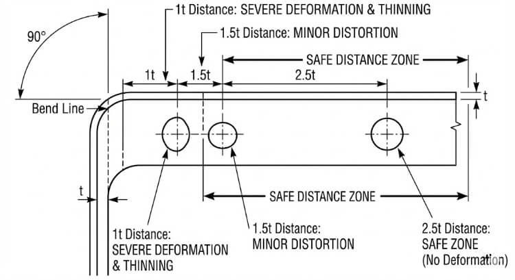
Отверстия, расположенные вблизи сгибов, часто деформируются. Когда лист сгибается, область вокруг линии сгиба растягивается, вытягивая материал возле отверстия. Это может привести к появлению трещин или изменению формы отверстия.
Чтобы избежать этого, располагайте отверстия на расстоянии не менее 1,5-2,5 т от линии сгиба. Для нержавеющей стали или высокопрочных материалов этот показатель следует увеличить до 3 т. Руководство SAE J2550 поддерживает эти значения, показывая, что они помогают сохранить форму отверстия при изгибе на 90°.
Тиснение и люверсы по краям
Тиснение и жалюзи делают лист прочнее, но ограничивают поток металла. Если они расположены слишком близко к кромке, напряжение нарастает, что приводит к растрескиванию или короблению кромки.
Обеспечьте зазор не менее 3 т от ближайшего края. Для более глубоких тиснений или жалюзи увеличьте расстояние до 4 т. Благодаря такому расстоянию края остаются ровными и не деформируются после формовки.
Формованные накладки и вырезы
Накладки и вырезы изменяют движение материала при гибке. Если они расположены слишком близко друг к другу, лист растягивается неравномерно. Это приводит к плохому качеству сгиба и несовместимым углам.
Располагайте выступы на расстоянии не менее 1 т друг от друга и 1,5 т от отверстий или изгибов. Это обеспечивает сбалансированное напряжение и плавное формование при производстве и сборке.
Ограничения геометрии конструкции и их влияние
Геометрия элементов влияет на то, как напряжение перемещается по металлу во время формовки. Соблюдение правил правильного расположения элементов помогает конструкторам более точно предсказать поведение при формовке.
Рекомендации по минимальному расстоянию
В промышленных стандартах расстояние между листами часто указывается как кратное толщине листа (t). В таблице ниже приведены общие рекомендации:
| Тип процесса | Характеристика отношений | Рекомендуемое расстояние | Комментарии |
|---|---|---|---|
| Гибка | Отверстие до линии изгиба | 1,5 т - 2,5 т | Общее правило проектирования |
| Резка кромки | Отверстие до края | ≥ 1.0t | Предотвращает разрывы кромок |
| Тиснение/рельеф по краям | 3t - 4t | Поддерживает плоскостность | |
| Глубокий рисунок | От черты к черте | ≥ 5t | Позволяет избежать проблем с истончением |
| Чеканка | От черты к черте | ≥ 2t | Снижает напряжение инструмента |
Это отправные точки. Точное расстояние между ними зависит от таких факторов, как прочность материала, угол изгиба и точность инструмента.
Радиус изгиба и взаимодействие элементов
Внутри радиус изгиба также влияет на то, насколько близко могут располагаться элементы. Меньший радиус увеличивает напряжение на изгибе. Если отверстие расположено слишком близко, оно может треснуть или деформироваться.
Располагайте отверстия на расстоянии не менее 1,5× радиуса изгиба. Для более твердых материалов, таких как нержавеющая сталь, увеличьте радиус до 2×. Большие радиусы помогают более равномерно распределить деформацию и улучшить целостность детали.
Когда расстояние и радиус хорошо сбалансированы, материал плавно изгибается, уменьшая пружина, деформация и повторная обработка.
Инструментарий и технологические аспекты
Взаимодействие штампов, пуансонов и прессовых инструментов напрямую ограничивает возможность близкого расположения элементов. Плохой доступ к инструменту или помехи могут повредить даже самую хорошо спроектированную деталь.
Зазор в матрице и доступ к инструменту
Для безопасной работы каждому пуансону и штампу требуется достаточно места. Если отверстия, выступы или тиснения расположены слишком близко друг к другу, траектории движения инструментов могут пересекаться. Это может привести к появлению царапин, заусенцев или поломке инструмента.
Чтобы предотвратить эти проблемы:
- Обеспечьте зазор не менее 1 т между элементами, имеющими одну и ту же траекторию движения инструмента.
- Для составных или прогрессивных штампов увеличьте зазор до 2t-3t, чтобы избежать перекрытия между штрихами.
- При изготовлении глубоких или многоступенчатых форм проведите моделирование оснастки перед резкой инструментальной стали.
Доступ к штампу имеет решающее значение при работе с листогибочными прессами и прогрессивными штампами. В листогибочном прессе узкое расстояние между пуансонами может препятствовать их правильному размещению между формованными участками. При прогрессивной штамповке разные пуансоны могут нанести удар по перекрывающимся областям, если компоновка слишком компактна. Использование 3D CAD валидации помогает обнаружить эти проблемы на ранней стадии и предотвратить дорогостоящую доработку инструмента.
Последовательность формовки и пружинящий откат
Порядок выполнения этапов формовки влияет на конечную точность. Когда детали расположены близко друг к другу, изгиб одной области может исказить другую. Например, формирование фланца рядом с жалюзи может сплющить или сместить высоту жалюзи.
Соблюдайте логическую последовательность формирования:
- Сначала сформируйте глубокие формы или тиснение.
- Далее выполните повороты.
- Завершите отделку и сделайте пирсинг.
Такая последовательность уменьшает передачу напряжения между элементами.
Еще одним фактором, на который следует обратить внимание, является пружинистость. После сгибания лист стремится вернуться в плоское состояние. Чем ближе расположены элементы, тем сильнее пружинящий эффект на соседних участках.
Способы борьбы с пружинящей спиной включают в себя:
- Увеличение радиуса изгиба.
- Добавление рестрайка или шага чеканки для стабилизации геометрии.
- Регулировка расстояния между элементами для уменьшения взаимодействия между областями.
Использование моделирования для прогнозирования и компенсации пружинящего отката помогает поддерживать стабильные углы и чистую геометрию в производственных деталях.
Методы моделирования и проверки
Перед началом серийного производства моделирование и испытания подтверждают безопасность правил расположения деталей. Эти этапы проверки связывают теорию проектирования с реальным поведением при формовании.
Анализ методом конечных элементов (FEA) в бесконтактных испытаниях
FEA позволяет инженерам увидеть, как напряжение и деформация перемещаются по металлу во время формовки. Если элементы расположены слишком близко друг к другу, образуются зоны повышенного напряжения - обычно в тех же местах, где впоследствии образуются трещины или морщины.
Такие программы, как AutoForm, ABAQUS и ANSYS, могут точно моделировать эти эффекты. Они показывают, как изменения расстояния между элементами, радиуса изгиба или типа материала влияют на утонение и пружинящий откат.
Основные результаты FEA включают:
- Карты распределения толщины: Покажите, где материал может слишком истончиться.
- Предельные диаграммы формования (FLD) указывают уровни деформации, при которых происходит разрыв.
- Графики контуров напряжений: Выделите участки с высокой нагрузкой рядом с отверстиями или тиснением.

Тестирование и корректировка прототипов
Даже при наличии детального моделирования все равно необходимы реальные испытания формования. Прототипы показывают, как ведет себя реальный материал в реальных условиях прессования, включая трение, износ инструмента и смазку.
Во время тестирования инженеры проверяют:
- Точность формы и положения отверстий.
- Соответствие угла изгиба и радиуса.
- Истончение или сморщивание поверхности вблизи сформированных элементов.
Если возникают проблемы, расстояние или радиус корректируются. В типичном случае результаты FEA сочетаются с данными физических испытаний. Как только оба варианта совпадают, макет готов к производству.
Стратегии оптимизации дизайна
Убедившись в надежности расстояния, следующим шагом будет оптимизация расположения с точки зрения производительности и внешнего вида.
Баланс между эстетикой и технологичностью
Дизайнеры иногда уменьшают расстояние между элементами, чтобы добиться компактности или визуального выравнивания макета. Хотя это выглядит чище, это может вызвать проблемы с формовкой, такие как деформация или растрескивание.
Лучший подход - выборочная регулировка. Увеличение расстояния даже на 0,5 т в ключевых зонах может предотвратить проблемы, сохраняя общий вид неизменным. Привлечение инженеров по оснастке на ранней стадии помогает найти эти точки равновесия до начала производства.
Тесная совместная работа дизайнеров и производственников обеспечивает сохранение эстетики и эффективности.
Стандартизация и библиотеки знаний
Создание внутренних библиотек правил приближения повышает согласованность. В эти базы данных заносятся проверенные соотношения для каждого материала и процесса, а также заметки из производственного опыта.
| Материал | Отверстие-изгиб | Рельефная кромка | Таб-таб | Источник |
|---|---|---|---|---|
| Алюминий 5052 | 1,5 т-2 т | 3t | 1t | Данные внутренних испытаний |
| SPCC из низкоуглеродистой стали | 2t | 3.5t | 1.5t | Отзывы о производстве |
| Нержавеющая сталь 304 | 2,5т-3т | 4t | 1.5t | Проверка инструментальной оснастки |
Такие рекомендации сокращают время проектирования, предотвращают повторные ошибки и помогают поддерживать неизменное качество формовки во всех проектах. Со временем эта общая база знаний приводит к улучшению конструкции, снижению затрат на оснастку и более плавному производству.
Распространенные ошибки в дизайне и как их избежать
Даже опытные конструкторы иногда упускают из виду правила расположения элементов. На чертеже эти ошибки могут выглядеть незначительными, но впоследствии они часто становятся причиной сбоев в формовке. Выявление таких ошибок на ранней стадии позволяет избежать отходов, износа инструмента и задержек в производстве.
Игнорирование направления зерен и потока материала
Частая ошибка - забыть о направлении зерна материала. Во время прокатки зерна металла выравниваются в одном направлении, что влияет на растяжение и изгиб листа.
Когда отверстия, прорези или тиснение расположены вдоль зерна, при гибке или вытяжке часто образуются трещины. Металл легче растягивается вдоль зерна, но сопротивляется растяжению поперек него, создавая слабые зоны. Эта проблема более заметна в нержавеющей стали и высокопрочных сплавах с низкой пластичностью.
Лучшие практики:
- По возможности располагайте отверстия и пазы перпендикулярно направлению зерна.
- Поверните глубокие элементы, такие как жалюзи или вытянутые чашки, так, чтобы они шли поперек долевой нити.
- Для деталей с жесткими ограничениями на формовку перед планированием раскладки запросите сертификаты прокатного стана с указанием ориентации зерна.
Контроль направления зерна помогает листу равномерно растягиваться, повышая точность, качество поверхности и усталостную прочность.
Переполненные макеты
Еще одна ошибка - втискивание слишком большого количества элементов в небольшое пространство для экономии материала или придания конструкции компактности. Перегруженность ограничивает поток металла при формовке, что повышает риск коробления, разрыва или деформации.
Например, в деталях кронштейнов отверстия, расположенные слишком близко к изгибам, могут удлиняться при формировании фланца. Слишком плотно расположенные люверсы могут перекрываться во время прессования, оставляя следы на поверхности или даже повреждая штамп.
Стратегии профилактики:
- Применяйте соотношение расстояний в зависимости от толщины листа (t) и типа формовки.
- Используйте моделирование FEA или испытания образцов для проверки сложных макетов.
- Перед выпуском проекта проведите анализ технологичности с инженерами по оснастке.
Перегруженная компоновка может выглядеть эффективно в САПР, но она часто увеличивает количество переделок, времени на проверку и брака. Сбалансированные конструкции обеспечивают лучшее качество и более стабильную производительность формования.
Заключение
Соблюдение правил расстановки - один из наиболее эффективных способов обеспечения стабильной формовки листового металла. Адекватное расстояние обеспечивает плавный поток материала, предотвращает появление трещин и поддерживает точность размеров. Это также защищает инструменты и сокращает количество брака, время наладки и перерывы в производстве.
Ранняя проверка с помощью моделирования и испытаний прототипов гарантирует, что конструкция будет хорошо работать в реальных условиях. Когда команды разработчиков, инструментальщиков и производственников работают вместе, они могут выявить риски, связанные с распоркой, на ранней стадии и добиться стабильных результатов формовки с меньшим количеством неожиданностей.
Готовы усилить конструкцию из листового металла?
Наша команда инженеров поможет проанализировать ваши макеты на предмет технологичности. Присылайте свои чертежи или 3D-моделиМы проверим предельные расстояния, смоделируем этапы формовки и порекомендуем улучшения до начала изготовления оснастки.
Часто задаваемые вопросы
Что произойдет, если отверстие окажется слишком близко к линии сгиба?
Отверстие может растянуться, деформироваться или треснуть во время формовки, поскольку материал вокруг изгиба деформируется неравномерно. Соблюдение зазора в 1,5-2,5 т помогает сохранить форму и прочность.
Как определить безопасные расстояния между отверстиями для нового материала?
Начните со стандартных соотношений, основанных на толщине листа и прочности на разрыв, а затем подтвердите результаты с помощью моделирования и испытаний прототипа.
Меняются ли правила расположения деталей при лазерной резке и перфорации?
Да. Перфорированные детали требуют большего расстояния, чтобы выдержать ударные нагрузки и предотвратить появление заусенцев или деформаций. Детали, вырезанные лазером, могут иметь меньшие расстояния, поскольку не подвергаются механическим нагрузкам.
Привет, я Кевин Ли

Последние 10 лет я занимался различными формами изготовления листового металла и делился здесь интересными идеями из своего опыта работы в различных мастерских.
Связаться
Кевин Ли
У меня более десяти лет профессионального опыта в производстве листового металла, специализирующегося на лазерной резке, гибке, сварке и методах обработки поверхности. Как технический директор Shengen, я стремлюсь решать сложные производственные задачи и внедрять инновации и качество в каждом проекте.
Связанный ресурс

Нержавеющая сталь с защитой от отпечатков пальцев: как это работает и как выбрать

OEM и контрактное производство: Как выбрать правильную модель для вашего проекта

Стоимость установки и стоимость единицы продукции при производстве листового металла
