Os engenheiros e fabricantes têm de assegurar medições exactas em peças e conjuntos. As tolerâncias controlam as variações, mas a escolha da tolerância correta é fundamental. Um mal-entendido pode levar a problemas de produção, falhas de montagem ou aumento de custos.
As tolerâncias unilaterais e bilaterais definem os desvios aceitáveis de formas diferentes. A utilização do tipo errado pode causar componentes incompatíveis, desperdício de materiais ou retrabalho dispendioso. Saber quando utilizar cada uma delas ajuda a manter a qualidade e a eficiência.
Vamos analisar as diferenças entre estes dois tipos de tolerância e quando utilizar cada um deles em projectos de engenharia.
Explicação da tolerância na conceção mecânica
A tolerância é um conceito-chave na engenharia. Define o quanto as dimensões de uma peça podem variar e ainda assim funcionar corretamente. Sem tolerâncias, as peças podem não se encaixar ou funcionar como pretendido.
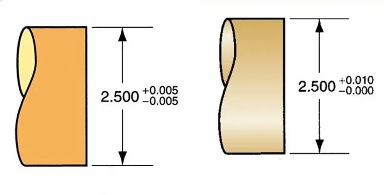
A tolerância define o intervalo de variação aceitável para as dimensões num desenho técnico. Por exemplo, se um eixo tiver um diâmetro de 10 mm com uma tolerância de ±0,05 mm, o eixo real pode medir entre 9,95 mm e 10,05 mm e ainda assim ser considerado razoável.
Todas as peças fabricadas têm alguma variação - nenhuma máquina pode fazer peças perfeitamente idênticas. As tolerâncias dão aos fabricantes limites claros sobre a quantidade de variação aceitável antes de uma peça ser rejeitada.
Estas tolerâncias aparecem nos desenhos técnicos como números após a dimensão principal, como 10±0,05 mm, ou como um intervalo, como 9,95-10,05 mm.
O que é a Tolerância Unilateral?
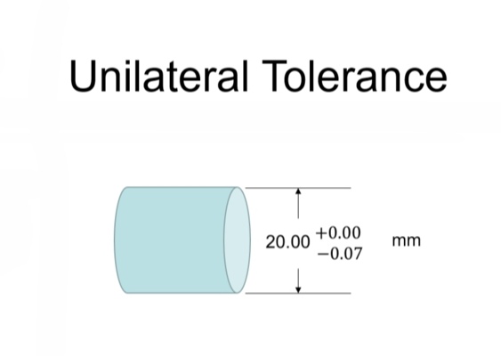
A tolerância unilateral é um tipo de tolerância dimensional em que a variação é permitida apenas numa direção (toda positiva ou toda negativa) da dimensão básica. Isto significa que a dimensão real de uma peça pode variar em relação à dimensão nominal apenas numa direção - maior ou menor, mas não em ambas.
Por exemplo, um veio pode ter um diâmetro de 20,00 mm com uma tolerância de +0,05/-0,00 mm. Esta tolerância unilateral significa que o diâmetro do veio pode ser até 20,05 mm mas não inferior a 20,00 mm. Do mesmo modo, um furo pode ter um diâmetro de 20,00 mm com uma tolerância de +0,00/-0,05 mm, o que significa que pode ser tão pequeno como 19,95 mm mas não maior do que 20,00 mm.
As tolerâncias unilaterais são normalmente utilizadas quando uma peça não deve exceder ou ficar abaixo de uma determinada dimensão limite por razões funcionais.
Como é que é aplicado em desenhos de engenharia?
Nos desenhos de engenharia, as tolerâncias unilaterais são marcadas para mostrar a variação numa só direção. A dimensão essencial é indicada, seguida do desvio permitido. Os engenheiros especificam se a tolerância é positiva (acima da dimensão essencial) ou negativa (abaixo da dimensão fundamental).
Os formatos mais comuns incluem:
- Método de dimensão direta: 20,00 +0,05/-0,00 mm
- Método da dimensão limite: 20,00-20,05 mm
- Método das notas: 20,00 mm +0,05 (ou -0,05 para tolerância unilateral negativa)
Representação da tolerância unilateral
As tolerâncias unilaterais seguem as práticas de notação padrão de acordo com as normas de desenho de engenharia:
- A dimensão essencial vem em primeiro lugar
- O desvio superior é seguido de um sinal de mais (+)
- O desvio inferior segue-se com um sinal de menos (-)
- Um destes desvios será zero na tolerância unilateral
Exemplos de aplicações de tolerância unilateral
- Diâmetros de veio para encaixe por pressão: Um veio com 15,00 +0,02/-0,00 mm assegura que o veio será sempre igual ou superior ao tamanho essencial, garantindo um ajuste apertado.
- Espessura mínima da parede dos recipientes sob pressão: A parede de um recipiente pode ser especificada como 8,00 +0,50/-0,00 mm, assegurando que a parede nunca é mais fina do que a espessura mínima de segurança.
- Posições dos orifícios da placa de circuitos: As localizações dos furos podem ter tolerâncias de ±0,00/+0,10 mm, assegurando que os componentes nunca interferem.
- Dimensões da altura máxima: Uma altura máxima pode ser especificada como 50,00 +0,00/-0,30 mm para peças que devem caber num espaço fixo.
Vantagens da tolerância unilateral
Controlo de fabrico mais fácil
A tolerância unilateral simplifica o fabrico ao concentrar-se numa direção de variação. Isto facilita o ajuste de ferramentas e processos para cumprir as especificações.
Inspeção simplificada e garantia de qualidade
A inspeção de peças com tolerância unilateral é simples. Os inspectores só precisam de verificar se a dimensão se encontra dentro do intervalo permitido numa direção, reduzindo o tempo e o esforço necessários para o controlo de qualidade.
O que é a Tolerância Bilateral?
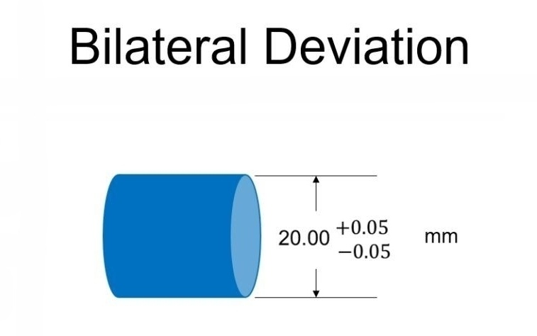
A tolerância bilateral é um tipo de tolerância dimensional em que a variação é permitida em ambas as direcções (positiva e negativa) em relação à dimensão essencial. Com a tolerância bilateral, a dimensão real de uma peça pode ser maior ou menor do que a dimensão nominal dentro de limites especificados.
Por exemplo, um eixo pode ter um diâmetro de 20,00 mm com uma tolerância bilateral de ±0,03 mm. Isto significa que o diâmetro do eixo pode variar de 19,97 mm a 20,03 mm e ainda assim ser considerado aceitável. A variação é distribuída em ambos os lados da dimensão básica.
As tolerâncias bilaterais são normalmente utilizadas para dimensões gerais em que pequenas variações em qualquer direção não afectam a função da peça.
Como é que é aplicado em desenhos de engenharia?
Nos desenhos de engenharia, as tolerâncias bilaterais são marcadas para mostrar variações iguais ou desiguais em ambas as direcções em relação à dimensão essencial. A dimensão fundamental é indicada em primeiro lugar, seguida dos desvios permitidos.
Os formatos mais comuns incluem:
- Igual bilateral: 20,00 ±0,03 mm (a variação é a mesma em ambas as direcções)
- Bilateral desigual: 20,00 +0,05/-0,02 mm (diferentes quantidades de variação em cada direção)
- Método da dimensão limite: 19,97-20,03 mm (com indicação direta dos limites mínimo e máximo)
Representação da Tolerância Bilateral
As tolerâncias bilaterais seguem a notação padrão de acordo com as normas de desenho de engenharia:
- A dimensão essencial vem em primeiro lugar
- Para tolerâncias bilaterais iguais, é utilizado um símbolo de mais/menos (±), seguido do valor do desvio
- Para tolerâncias bilaterais desiguais, são fornecidos o desvio superior com um sinal de mais (+) e o desvio inferior com um sinal de menos (-)
- Ambos os desvios têm valores diferentes de zero na tolerância bilateral
Exemplos de aplicações de tolerância bilateral
- Dimensões gerais dos componentes maquinados: A largura de uma placa pode ser especificada como 100,00 ±0,50 mm para aplicações de uso geral.
- Diâmetros de furos para encaixes deslizantes: Para obter o equilíbrio de ajuste correto, um furo de rolamento pode ser especificado como 25,00 +0,02/-0,01 mm.
- Largura do traço da placa de circuito impresso: Os traços das placas de circuitos podem ter tolerâncias de largura de 0,50 ±0,05 mm para manter o desempenho elétrico e, ao mesmo tempo, acomodar a variabilidade de fabrico.
- Dobragem de chapa metálica dimensões: Um ângulo de curvatura pode ser especificado como 90° ±1° para ter em conta mola de retorno e variações de ferramentas.
- Moldagem de peças plásticas: Peças moldadas por injeção utilizam frequentemente tolerâncias bilaterais, como 30,00 ±0,20 mm, para a contração do material e o desgaste do molde.
Vantagens da tolerância bilateral
Distribuição equilibrada de materiais
A tolerância bilateral permite que o material seja adicionado ou removido de forma igual. Isto ajuda a manter o equilíbrio no design da peça e reduz as concentrações de tensão.
Maior flexibilidade no fabrico
Os fabricantes têm mais flexibilidade com a tolerância bilateral. Podem ajustar ferramentas e processos para se manterem dentro da gama de tolerância sem se preocuparem com uma única direção de variação. Isto conduz frequentemente a uma produção mais rápida e a custos mais baixos.
Principais diferenças entre a tolerância unilateral e a bilateral
Compreender as diferenças de tolerância unilateral e bilateral ajuda os engenheiros a escolher a abordagem de projeto correta. Aqui está uma descrição das principais distinções:
Definição
- Tolerância unilateral: Permite a variação apenas numa direção em relação ao tamanho nominal (maior ou menor).
- Tolerância bilateral: Permite a variação do tamanho nominal (maior e menor).
Direção da variação
- Tolerância unilateral: A variação é limitada a um lado da dimensão nominal. Por exemplo, 10 mm +0,2/-0 significa que a peça pode ser até 0,2 mm maior, mas não menor.
- Tolerância bilateral: A variação é permitida em ambos os lados da dimensão nominal. Por exemplo, 10 mm ±0,1 mm significa que a peça pode ser 0,1 mm maior ou menor.
Intenção de conceção
- Tolerância unilateral: Utilizado quando o ajuste preciso numa direção é crítico. Por exemplo, um eixo não deve exceder um tamanho específico para encaixar num orifício.
- Tolerância bilateral: Utilizado quando são aceitáveis ligeiras variações em ambos os lados da dimensão nominal. Por exemplo, as dimensões de um suporte podem variar ligeiramente sem afetar a sua função.
Flexibilidade de fabrico
- Tolerância unilateral: Limita a flexibilidade de fabrico porque a variação só é permitida numa direção. Este facto pode aumentar os custos se a tolerância for apertada.
- Tolerância bilateral: Oferece maior flexibilidade porque a variação é permitida em ambas as direcções. Isto torna muitas vezes mais fácil e mais económica a produção de peças.
| Aspeto | Tolerância unilateral | Tolerância bilateral |
|---|---|---|
| Definição | A variação só é permitida numa direção (maior ou menor). | Variação permitida em ambas as direcções (maior e menor). |
| Direção da variação | Unilateral (por exemplo, +0,2/-0 ou +0/-0,2). | Dois lados (por exemplo, ±0,1). |
| Intenção de conceção | Utilizado quando é fundamental um ajuste preciso numa direção. | Utilizado quando são aceitáveis ligeiras variações em ambos os lados. |
| Flexibilidade de fabrico | Menos flexível; controlo mais apertado numa direção. | Mais flexível; mais fácil de realizar na produção. |
Outros tipos de tolerâncias de engenharia
Para além das tolerâncias unilaterais e bilaterais, os engenheiros utilizam vários outros tipos de tolerância importantes para controlar vários aspectos da qualidade e função da peça. Cada uma serve necessidades específicas de design e cenários de fabrico.
Dimensionamento Geométrico e Tolerância (GD&T)
O GD&T é um sistema abrangente que vai para além das simples tolerâncias dimensionais. Controla caraterísticas geométricas como a forma, a orientação, a localização e a excentricidade. Este sistema utiliza símbolos e regras para definir a forma exacta e os requisitos de posição das caraterísticas numa peça.
Os principais tipos de tolerância GD&T incluem:
- Tolerâncias de forma: Controlar a retidão, a planicidade, a circularidade e a cilindricidade
- Tolerâncias de orientação: Controlar o paralelismo, a perpendicularidade e a angularidade
- Tolerâncias de localização: Posição de controlo, concentricidade e simetria
- Tolerâncias de batimento: Controlo da excentricidade circular e total
A GD&T proporciona um controlo mais preciso da geometria das peças do que a tolerância dimensional tradicional.
Tolerâncias estatísticas
A tolerância estatística utiliza a probabilidade e a estatística para prever como as variações nas dimensões individuais irão afetar uma montagem. Ao contrário da tolerância do pior caso, que assume que todas as peças estão nos seus limites extremos, a tolerância estatística reconhece que a maioria das peças estará mais próxima da dimensão nominal.
Esta abordagem utiliza símbolos como "ST" ou "RSS" (Root Sum Square) nos desenhos para indicar onde se aplicam os métodos estatísticos. Permite frequentemente tolerâncias individuais mais alargadas, mantendo a qualidade global da montagem.
Tolerâncias de limite
A tolerância de limite especifica diretamente as dimensões máximas e mínimas permitidas sem fazer referência a uma dimensão essencial. Por exemplo, o diâmetro de um eixo pode ser de 15,02-15,05 mm.
Este método comunica a gama aceitável e é frequentemente utilizado em ambientes de produção onde são efectuadas comparações diretas de medições.
Tolerâncias de ajuste
As tolerâncias de ajuste controlam a forma como as peças interagem quando montadas. Definem a folga ou a interferência entre as peças que se encaixam. Os sistemas de ajuste padrão incluem:
- Ajustes de folga: O furo é sempre mais significativo do que o eixo, permitindo a livre circulação
- Ajustes de interferência: O eixo é sempre mais significativo do que o furo, criando um encaixe de pressão
- Ajustes de transição: Por vezes com folga, por vezes com interferência, dependendo dos tamanhos actuais
As tolerâncias de ajuste são normalmente definidas de acordo com sistemas normalizados como ISO ou ANSI, com designações como H7/f7 (ajuste de folga) ou H7/s6 (ajuste de interferência).
Tolerâncias não uniformes
As tolerâncias não uniformes variam ao longo do comprimento ou da área de uma caraterística. Por exemplo, um veio cónico pode ter tolerâncias mais apertadas na superfície do rolamento e tolerâncias mais soltas noutros locais. Esta abordagem optimiza os custos de fabrico, aplicando tolerâncias apertadas apenas onde for funcionalmente necessário.
Tolerâncias de perfil
As tolerâncias de perfil controlam a forma geral de uma superfície, especificando o quanto esta se pode desviar da forma perfeita teórica. São frequentemente utilizadas para superfícies curvas complexas ou caraterísticas estéticas.
As tolerâncias de perfil podem ser aplicadas a:
- Perfis de linha (2D)
- Perfis de superfície (3D)
São normalmente utilizados em painéis de carroçarias de automóveis, produtos de consumo e componentes aeroespaciais.
Modificadores de condição do material
Estes modificadores ajustam as zonas de tolerância com base no tamanho real de uma caraterística:
- Condição máxima do material (MMC): Aplica-se quando a caraterística contém mais material
- Condição menos material (LMC): Aplica-se quando a caraterística inclui o mínimo de material
- Independentemente do tamanho da caraterística (RFS): Aplica-se independentemente do tamanho real da caraterística
Estes modificadores ajudam a garantir que as peças se encaixam corretamente, maximizando a flexibilidade de fabrico.
Conclusão
As tolerâncias de engenharia desempenham um papel crucial na conceção e fabrico de peças de qualidade. As tolerâncias unilaterais e bilaterais representam duas abordagens fundamentais para o controlo da variação dimensional.
A escolha entre estes tipos de tolerância depende dos requisitos específicos do projeto, das capacidades de fabrico e das considerações de custo. Os engenheiros devem considerar a função de cada caraterística, os processos de fabrico disponíveis e os métodos de inspeção ao selecionar o tipo de tolerância adequado.
Na Shengen, prestamos serviços de fabrico de chapas metálicas e de fabrico de precisão de elevada qualidade. Quer necessite de ajuda com tolerâncias, prototipagem ou produção em massa, a nossa equipa experiente está aqui para o apoiar. Contate-nos hoje para discutir o seu projeto e obter um orçamento gratuito!
Olá, chamo-me Kevin Lee

Nos últimos 10 anos, tenho estado imerso em várias formas de fabrico de chapas metálicas, partilhando aqui ideias interessantes a partir das minhas experiências em diversas oficinas.
Entrar em contacto
Kevin Lee
Tenho mais de dez anos de experiência profissional no fabrico de chapas metálicas, especializando-me em corte a laser, dobragem, soldadura e técnicas de tratamento de superfícies. Como Diretor Técnico da Shengen, estou empenhado em resolver desafios complexos de fabrico e em promover a inovação e a qualidade em cada projeto.
Recursos relacionados

Aço inoxidável resistente a impressões digitais: como funciona e como escolher

OEM vs. fabrico por contrato: Como escolher o modelo certo para o seu projeto

Custo de instalação vs. custo unitário no fabrico de chapas metálicas
