Os projectistas debatem-se frequentemente para garantir que as peças se encaixam bem. Superfícies irregulares podem causar problemas na montagem, criar encaixes deficientes e até levar a falhas no produto. O controlo da planeza em GD&T oferece uma forma clara de verificar e corrigir este problema. Quando se sabe como utilizar a planeza, é possível reduzir o retrabalho, poupar custos e tornar a produção mais consistente.
A planeza pode parecer uma ideia simples, mas a sua implementação levanta muitas vezes questões. Iremos analisar o que significa, como medi-la e como utilizá-la no design.
O que é a planeza em GD&T?
A planeza em GD&T mostra quão perto uma superfície está de ser perfeitamente uniforme em todos os pontos. Controla o quanto uma superfície pode variar em altura. Para o efeito, a planeza define uma zona de tolerância constituída por dois planos paralelos. A superfície da peça deve ficar entre estes dois planos. Isto evita dobras, ondas ou saliências que podem causar problemas durante a montagem.
A zona de tolerância para a planeza é simples. O valor apresentado no quadro de controlo da caraterística define dois planos paralelos entre si. A superfície deve caber entre estes planos em todos os pontos.
Se alguma parte da superfície sair desta zona, a peça não cumpre o projeto. Por exemplo, se a tolerância de planeza for de 0,05 mm, a altura da superfície só pode variar dentro de 0,05 mm em toda a área.
Símbolo e normas
A planeza em GD&T utiliza um símbolo simples que é facilmente reconhecível nos desenhos. As normas ASME e ISO definem como este símbolo deve ser apresentado e como a tolerância deve ser aplicada.
O símbolo de planeza GD&T
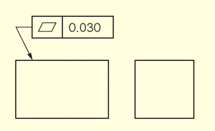
O símbolo da planeza é um paralelogramo. Aparece dentro de um quadro de controlo de caraterística juntamente com o valor de tolerância. Por exemplo, se a moldura apresentar o símbolo de planeza com 0,1, a superfície tem de se manter dentro de dois planos paralelos que estejam separados por 0,1 mm.
A planeza não necessita de um ponto de referência, o que a distingue de muitos outros controlos GD&T que dependem de caraterísticas de referência. Por este motivo, a planeza é uma forma direta de controlar uma única superfície sem a associar a outras partes do desenho.
Normas de planeza em ASME e ISO
A ASME Y14.5 é a norma GD&T mais comum nos Estados Unidos. Fornece regras detalhadas para a aplicação do símbolo de planicidade, a definição da zona de tolerância e a verificação de peças durante a inspeção.
A ISO 1101 é a principal norma internacional. Segue a mesma ideia básica, mas por vezes utiliza formas diferentes de apresentar símbolos ou molduras. Por exemplo, o estilo ou a colocação podem nem sempre corresponder aos desenhos ASME.
Como a planicidade é aplicada no design?
A planicidade é um controlo útil no design. Indica aos fabricantes exatamente o grau de regularidade de uma superfície, eliminando quaisquer conjecturas. Quando os engenheiros adicionam a planeza aos desenhos, asseguram que as superfícies chave funcionam como pretendido.
Indicação da planeza nos desenhos técnicos
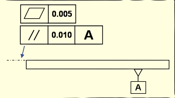
Os desenhos técnicos mostram a planeza com um quadro de controlo de caraterísticas. O quadro inclui o símbolo de planeza e o valor de tolerância. Pode ser fixada à superfície com uma linha de referência ou colocada diretamente por baixo da dimensão.
Por exemplo, se uma superfície tiver uma tolerância de planeza de 0,05 mm, o quadro mostrará o símbolo de planeza e o número 0,05. Isto significa que a superfície deve manter-se dentro de dois planos paralelos separados por 0,05 mm em cada ponto.
Caraterísticas comuns em que a planeza é especificada
A planicidade é frequentemente necessária para grandes superfícies planas que se juntam a outras peças. Exemplos incluem bases de montagem, faces de vedação, áreas de juntas e tampas de caixas. Estas superfícies têm de ser planas para evitar folgas, fugas ou pressões irregulares na montagem.
A planeza também é comum em peças finas, como chapas de metal. Estas peças podem deformar-se durante a maquinagem ou tratamento térmico. Ao adicionar tolerâncias de planicidade, os engenheiros podem controlar melhor a distorção e manter a superfície dentro dos limites necessários.
Métodos de medição da planeza
Medir a planeza é tão importante como defini-la. Os engenheiros e inspectores escolhem diferentes ferramentas com base no tamanho da peça, no nível de tolerância e na precisão necessária. Cada método tem as suas próprias vantagens e limites.
Placa de superfície e medidor de altura
Uma placa de superfície fornece um plano de referência preciso. A peça é colocada sobre a placa e um medidor de altura ou sonda verifica pontos ao longo da superfície. As diferenças nas leituras mostram o quanto a superfície varia. Este método é simples, económico e amplamente utilizado em oficinas.
Indicador de marcação
Um relógio comparador pode ser montado num suporte e utilizado com uma placa de superfície. A peça assenta na placa enquanto a ponta do indicador toca em vários pontos da superfície. À medida que a peça se move, o mostrador indica as alterações na altura. Este método é rápido, fácil de utilizar e bom para verificações de rotina.
Máquinas de medição por coordenadas (CMMs)
As máquinas de medição por coordenadas proporcionam uma maior precisão. Utilizam sondas para medir muitos pontos numa superfície e depois calculam a planicidade a partir dos dados. Os resultados são precisos e repetíveis, e incluem relatórios detalhados para registos de qualidade. As máquinas de medição por coordenadas são melhores para tolerâncias apertadas ou peças com formas complexas.
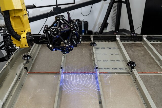
Sistemas ópticos e laser
As ferramentas ópticas e laser permitem medições sem contacto. Dispositivos como scanners laser e interferómetros podem captar milhares de pontos rapidamente. Estes sistemas são úteis para peças delicadas que não podem ser tocadas ou para superfícies muito grandes. Fornecem mapas de superfície pormenorizados que mostram até pequenas variações.
Factores que afectam o nivelamento
Vários factores podem tornar uma superfície irregular ou deformada. Compreendê-los ajuda a evitar problemas na produção.
Propriedades do material e temperatura
O tipo de material afecta fortemente a planicidade. Os metais mais macios, como o alumínio, podem dobrar-se ou deformar-se mais facilmente. Os metais mais duros, como o aço, resistem à flexão, mas podem conter tensões internas. As alterações de temperatura também são importantes. Quando uma peça aquece ou arrefece, expande-se ou contrai-se. Um aquecimento desigual pode fazer com que um lado se mova mais do que o outro, causando deformações. Isto acontece frequentemente durante soldadura, fundiçãoou tratamento térmico.
Processos de fabrico e desgaste de ferramentas
Os diferentes métodos de fabrico afectam a planicidade da superfície de várias formas. Fresagem, esmerilhamento, estampageme corte a laser todos produzem resultados diferentes. As ferramentas gastas agravam os problemas de planicidade. As ferramentas gastas cortam de forma desigual, criando pontos altos e baixos na superfície. A manutenção regular das ferramentas e as velocidades de corte adequadas ajudam a reduzir estes problemas.
Tensões residuais e deformação
As tensões residuais são forças retidas no interior de uma peça depois de esta ter sido fabricada. Estas tensões podem dobrar ou torcer o material mesmo após a maquinação. Processos como soldadura, fundição ou dobragem de chapa metálica deixam frequentemente tensões residuais. Com o tempo, estas tensões podem relaxar, alterando a planicidade da superfície. Tratamentos como o alívio de tensões ou passos de maquinagem controlados podem reduzir estes riscos e estabilizar as superfícies.
Melhores práticas para engenheiros e projectistas
Os requisitos de planeza devem equilibrar a função da peça e a capacidade de fabrico. Para obter a planicidade correta, é necessário um design inteligente e uma comunicação clara.
Definição de requisitos práticos de planeza
A planicidade deve corresponder ao objetivo da peça. Poderão ser necessárias tolerâncias apertadas para evitar fugas numa superfície de vedação, mas uma tolerância mais folgada poderá funcionar bem numa placa de montagem. A escolha de uma tolerância mais rigorosa do que a necessária pode aumentar os custos sem melhorar o desempenho.
Comunicar a planeza de forma clara nos desenhos
Os desenhos devem mostrar a planeza de forma clara e consistente. Coloque o quadro de controlo de caraterísticas perto da superfície ou dimensão relevante e assegure-se de que o valor da tolerância é facilmente legível. Evitar notas vagas ou símbolos pouco claros que possam ser mal interpretados.
Colaboração com os fabricantes
Os bons resultados dependem de uma forte comunicação com os fabricantes. Os engenheiros devem discutir as escolhas de tolerância com os maquinistas no início do processo de conceção. Isto assegura que a planicidade escolhida pode ser alcançada com as ferramentas e métodos disponíveis. A colaboração também pode revelar ajustes que poupam custos, como pequenas alterações na tolerância ou no acabamento da superfície.
Conclusão
A planeza em GD&T define regras claras para a uniformidade de uma superfície. Ajuda as peças a encaixarem-se umas nas outras, reduz a tensão nas montagens e melhora a fiabilidade do produto. Ao aplicar corretamente a planeza, os engenheiros podem evitar retrabalhos dispendiosos, poupar tempo na produção e garantir um melhor desempenho em muitas indústrias.
Necessita de peças de alta qualidade com um controlo rigoroso da planicidade? Contacte-nos hoje para discutir o seu projeto e obter uma solução rápida e fiável adaptada às suas necessidades.
Olá, chamo-me Kevin Lee

Nos últimos 10 anos, tenho estado imerso em várias formas de fabrico de chapas metálicas, partilhando aqui ideias interessantes a partir das minhas experiências em diversas oficinas.
Entrar em contacto
Kevin Lee
Tenho mais de dez anos de experiência profissional no fabrico de chapas metálicas, especializando-me em corte a laser, dobragem, soldadura e técnicas de tratamento de superfícies. Como Diretor Técnico da Shengen, estou empenhado em resolver desafios complexos de fabrico e em promover a inovação e a qualidade em cada projeto.
Recursos relacionados

Aço inoxidável resistente a impressões digitais: como funciona e como escolher

OEM vs. fabrico por contrato: Como escolher o modelo certo para o seu projeto

Custo de instalação vs. custo unitário no fabrico de chapas metálicas
