Obudowy blaszane chronią niezbędną elektronikę. Mogą one jednak również zatrzymywać ciepło. Gdy ciepło gromadzi się i nie ma dokąd uciec, temperatura wewnętrzna może gwałtownie wzrosnąć. Wzrost ten może powodować dławienie, nagłe resety lub krótszą żywotność podzespołów. Wielu inżynierów kieruje się prostą zasadą: każde dodatkowe 10°C może skrócić żywotność komponentu o połowę.
Dlatego wentylacja jest kluczowym elementem konstrukcji obudowy. Nie jest to wybór kosmetyczny. Skuteczne planowanie przepływu powietrza pomaga utrzymać stałą temperaturę. Zapewnia również stabilną wydajność i dłuższą żywotność. W wielu przypadkach poprawia nawet bezpieczeństwo całego systemu.
Niniejszy przewodnik wyjaśnia praktyczne metody dodawania wentylacji do obudów blaszanych. Każda metoda została sprawdzona w rzeczywistych projektach. Pomysły te umożliwiają inżynierom projektowanie opłacalnych i prostych ścieżek przepływu powietrza do zastosowań przemysłowych, komercyjnych i zewnętrznych.
Dlaczego wentylacja ma kluczowe znaczenie w obudowach blaszanych?
Projektując obudowę blaszaną, często skupiamy się na rozmiarze, montażu i wykończeniu powierzchni. Wentylacja jest jednak równie ważna. Części elektroniczne generują ciepło, a ciepło to wymaga wyraźnej drogi ucieczki z obudowy. Sam metal nie jest w stanie sobie z tym poradzić.
Wzrost temperatury może wydawać się powolny, ale jego wpływ szybko staje się widoczny. Urządzenie o mocy 20-30 W w zamkniętej obudowie może podnieść temperaturę wewnętrzną o 15-25°C. Taki wzrost może skrócić żywotność komponentów, obniżyć wydajność, a nawet spowodować wyłączenie. Dobra wentylacja utrzymuje temperaturę na stabilnym poziomie. Zmniejsza również awaryjność i zapewnia bezpieczniejsze użytkowanie przez długi czas.
Opcje wentylacji pasywnej
Pasywny przepływ powietrza opiera się na naturalnym ruchu powietrza, a nie na wykorzystaniu wentylatorów. Działa dobrze, gdy obciążenia cieplne są umiarkowane, a warunki instalacji stabilne. Poniżej przedstawiono trzy standardowe metody pasywne.
Wycięcia - otwory, szczeliny i niestandardowe wzory
Wycięcia zapewniają łatwy przepływ powietrza do i z obudowy. Można użyć okrągłych otworów, długich szczelin lub niestandardowych kształtów. Każda opcja ma swoje zalety, ale ich wydajność może się różnić.
Co działa dobrze:
- Szczeliny w dolnej części ułatwiają wlot chłodnego powietrza i pozwalają ciepłemu powietrzu unosić się i wylatywać.
- Jednolite wzory zapewniają przewidywalną i prostą produkcję.
- Unikaj bardzo gęstych skupisk małych otworów w cienkim metalu, ponieważ mogą one powodować wypaczenia.
Porady dotyczące produkcji:
- Ustaw minimalną średnicę otworu na około 1,2-krotność grubości arkusza.
- Metal między otworami powinien mieć co najmniej 1× grubość.
- Unikaj umieszczania otworów w pobliżu linii zgięcia. Należy dążyć do odległości co najmniej 2× grubość.
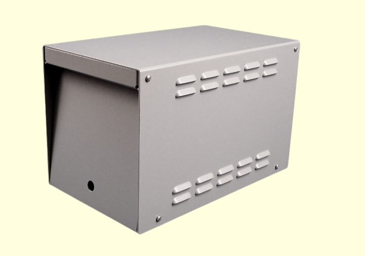
Żaluzje i otwory wentylacyjne labiryntowe
Na zewnątrz lub w miejscach o dużym zapyleniu otwarte otwory mogą nie zapewniać wystarczającej ochrony. Żaluzje Rozwiązaniem tego problemu jest zastosowanie kątowych łopatek, które blokują bezpośredni wlot pyłu lub deszczu, jednocześnie umożliwiając przepływ powietrza.
Kluczowe wskazówki dotyczące umieszczania:
- W przypadku obudów zewnętrznych należy skierować żaluzje w dół lub umieścić je po bokach. Należy unikać otworów wentylacyjnych skierowanych do góry.
- Dopasuj kąt ostrza do rzeczywistych warunków instalacji.
- Spodziewaj się, że przepływ powietrza spadnie o 15-30% w porównaniu z otwartymi wycięciami, więc zaplanuj obszar wentylacji, mając to na uwadze.
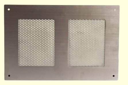
Panele perforowane dla obszarów o wysokim przepływie
Perforowany metal jest idealny, gdy wymagany jest silny przepływ powietrza przy zachowaniu dobrej wytrzymałości i czystego wyglądu. Panele te wykorzystują regularne wzory otworów i mogą zastąpić cały płaski panel lub zostać dodane jako wkładki.
Na co zwrócić uwagę:
- Typowe współczynniki otwartej powierzchni wahają się od 20% do 40%.
- Grubsze arkusze pozostają sztywne i odporne na zginanie lub wypaczanie.
- Jeśli farba proszkowa Lub anodować panelu, upewnij się, że powłoka nie wpływa na kształt otworu.
- Koszty są często niższe niż w przypadku wycinania laserowego wielu małych otworów, zwłaszcza na dużych powierzchniach.
Przykładowy przypadek użycia:
Obudowa przyrządu wykorzystywała kiedyś tylko 6% otwartej przestrzeni do wentylacji. Po przejściu na perforowany panel o otwartej powierzchni około 28%, temperatura wewnętrzna spadła o 12-18 °C. Wentylator nie był potrzebny.
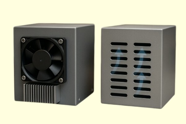
Opcje aktywnej wentylacji
Pasywny przepływ powietrza jest odpowiedni dla umiarkowanego ciepła, ale staje się mniej skuteczny, gdy poziom mocy wzrasta lub komponenty są umieszczone blisko siebie. W takich przypadkach naturalna konwekcja nie jest w stanie usunąć ciepła wystarczająco szybko. Aktywne chłodzenie wykorzystuje wentylatory lub dmuchawy do cyrkulacji powietrza w obudowie, zapewniając stałą i przewidywalną kontrolę temperatury.
Aktywna wentylacja pomaga, gdy:
- Obciążenie cieplne powyżej 25-30 W w ciasnej przestrzeni
- Kilka źródeł ciepła znajduje się w tym samym obszarze
- Powietrze musi przemieszczać się przez małe szczeliny lub kanały
- Środowisko jest ciepłe lub ma ograniczony przepływ powietrza
- Temperaturę wewnętrzną należy utrzymywać w określonym zakresie
Poniżej znajdują się praktyczne sposoby na włączenie aktywnego chłodzenia i utrzymanie stabilnej wydajności termicznej.
Wybór wentylatora i wydajność przepływu powietrza
Wybór wentylatora to coś więcej niż tylko wybór rozmiaru lub uwzględnienie znamionowej wartości CFM. Rzeczywisty przepływ powietrza zależy od oporu wewnątrz obudowy.
Zrozumienie CFM i wzrostu temperatury
Prostym sposobem oszacowania przepływu powietrza jest
Wymagane CFM ≈ Obciążenie cieplne (W) ÷ (1,2 × dopuszczalny wzrost temperatury °C)
Przykładowo, obciążenie o mocy 60 W z ograniczeniem wzrostu temperatury do 15°C wymaga około 3,3 CFM swobodnego powietrza. Gdy otwory wentylacyjne, filtry, żaluzje lub ciasne przestrzenie wewnętrzne zwiększają opór, przepływ powietrza spada. Margines bezpieczeństwa 30-80% pomaga zapewnić wydajność w rzeczywistym użytkowaniu.
Ciśnienie statyczne ma znaczenie
Systemy z ograniczonymi otworami wentylacyjnymi, perforowanymi panelami lub przeszkodami wewnętrznymi wymagają wentylatorów o wyższym ciśnieniu statycznym.
- Wentylatory osiowe poruszają dużą ilością powietrza, ale mają trudności z efektywnym radzeniem sobie z oporem.
- Dmuchawy utrzymują silny przepływ powietrza nawet przy ograniczeniach i dobrze współpracują z kanałami lub filtrami.
- Fani styczniowi równomiernie rozprowadza strumień powietrza na długich płytkach PCB lub powierzchniach obudowy.
Odpowiedni typ wentylatora zapewnia, że powietrze dociera do gorących komponentów zamiast uciekać przez najbliższy otwór.
Prawidłowe rozmieszczenie wentylatorów
Umiejscowienie wentylatora często ma większy wpływ na chłodzenie niż sam model wentylatora.
Ogólne wytyczne:
- Umieść wlot nisko, a wylot wysoko, aby wspierać naturalną konwekcję.
- Utrzymuj wlot i wylot tak daleko od siebie, jak to możliwe, aby uniknąć zwarcia przepływu powietrza.
- Należy unikać montowania wentylatorów bezpośrednio przy solidnych panelach.
- Zachować 25-40 mm wolnej przestrzeni na wlocie wentylatora.
Typowe błędy:
- Wlot i wylot po tej samej stronie
- Wentylatory dmuchające w narożniki bez ścieżki wyjścia
- Wentylatory umieszczone zbyt blisko żaluzji o wysokiej rezystancji
- Wiązki kabli blokujące wlot lub wylot wentylatora
Korzystanie z kanałów i prowadnic przepływu powietrza
Same wentylatory nie mogą zagwarantować, że powietrze będzie przemieszczać się nad częściami, które tego najbardziej potrzebują. Wewnętrzne kanały lub prowadnice pomagają kształtować ścieżkę przepływu powietrza.
Dlaczego kanały pomagają:
Powietrze szuka ścieżki najmniejszego oporu. Bez wskazówek, przepływ powietrza często:
- Opuszcza obudowę przez najbliższy otwór wentylacyjny
- Porusza się wokół gorących elementów zamiast w poprzek nich
- Tworzy zastałe, ciepłe strefy po drugiej stronie obudowy.
Proste kanały mogą:
- Wymuszanie przepływu powietrza przez radiatory
- Oddzielne strefy gorące i chłodne
- Zapobieganie obejściowemu przepływowi powietrza
- Lepsze chłodzenie bez wyższych prędkości wentylatora
Przykład:
Mała płyta CPU osiągnęła temperaturę 80 °C nawet z wentylatorem. Powietrze uciekało na boki zamiast przecinać radiator. Dodanie małego kanału z blachy przepchnęło powietrze przez żebra i obniżyło temperaturę do około 62 °C.
Projektowanie czystej ścieżki przepływu powietrza
Przepływ powietrza działa najlepiej, gdy podąża prostą, bezpośrednią trasą. Preferowany kierunek należy wybrać na jak najwcześniejszym etapie procesu projektowania.
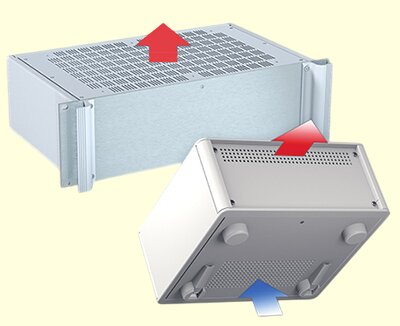
Typowe wzorce przepływu powietrza:
- Przód-tył: Dobry do urządzeń typu rack lub chassis
- Od dołu do góry: Działa dobrze w przypadku naturalnej konwekcji i skrzynek naściennych
- Z boku na bok: Odpowiedni, gdy przednie lub tylne otwory są zablokowane
W przypadku każdego wzoru należy się upewnić:
- Chłodne powietrze dociera do wszystkich głównych źródeł ciepła
- Gorące powietrze wydostaje się w najwyższym możliwym punkcie
- Kable, wsporniki i osłony nie blokują przepływu.
Przykład przed i po:
- Przed: Wlot i wylot po lewej → pętla przepływu powietrza, gorący punkt pozostał
- Po: Wlot po lewej, powietrze kierowane przez PCB, wylot po prawej → temperatura spadła o 11-17 °C
Wytyczne DFM dotyczące funkcji wentylacji
Po wybraniu metody wentylacji, następnym krokiem jest upewnienie się, że można ją łatwo wyprodukować. Dobrze DFM utrzymuje panele płasko, skraca czas cięcia i pomaga kontrolować koszty.
Zarządzanie gęstością otworów i szczelin
Wycinane laserowo Wzory wyglądają czysto, ale gęste grupy otworów mogą powodować zniekształcenia cieplne. Metal nagrzewa się podczas cięcia, a cienkie sekcje stają się bardziej podatne na wypaczenia. Poniższe wskazówki pomogą uniknąć tych problemów:
- Minimalna średnica otworu powinna być około 1,2 razy większa od grubości arkusza.
- Utrzymuj metal między otworami na poziomie co najmniej 1× grubości.
- Zachowaj 2-3× grubość z dala od linii zgięcia.
- Unikaj współczynników otwartej powierzchni powyżej 45-55% na cienkich materiałach.
- Podziel duże obszary wentylacyjne na mniejsze strefy, aby zmniejszyć gromadzenie się ciepła podczas cięcia.
Zasady te pozwalają zachować wytrzymałość i płaskość panelu, szczególnie w przypadku stosowania cienkiego aluminium lub cienkiej stali.
Uwagi dotyczące formowanych żaluzji
Żaluzje wymagają procesu wykrawania i formowania, więc odstępy i kształt mają kluczowe znaczenie. Zły projekt może prowadzić do niespójnego formowania lub osłabionych obszarów.
- Długość żaluzji powinna wynosić co najmniej 20-25 mm dla stabilnego formowania.
- Kąt nachylenia łopatek od 30° do 55° zapewnia niezawodny przepływ powietrza.
- Zachować odstępy między żaluzjami równe co najmniej 1,5-krotności grubości materiału.
- Należy unikać umieszczania żaluzji w pobliżu zakrętów lub narożników.
Żaluzje naturalnie usztywniają panel, ale zbyt wiele w tym samym obszarze może powodować nierównomierne naprężenia. Jeśli panel zaczyna się wyginać, należy dodać wzmocnienie.
Integracja paneli perforowanych
Perforowany arkusz sprawdza się dobrze w przypadku dużych sekcji przepływu powietrza, ale wymaga odpowiedniego podparcia, aby pozostać sztywnym i płaskim.
- Zachowaj co najmniej 8-12 mm solidnej krawędzi do montażu.
- Unikaj umieszczania elementów złącznych w perforowanych obszarach.
- Dodaj kołnierze lub kolanka powrotne, aby ograniczyć "puszkowanie oleju".
- Upewnij się, że procesy wykończeniowe nie zatykają małych otworów.
Perforowane panele zapewniają silny i równomierny przepływ powietrza oraz skracają czas cięcia, gdy obszary wentylacyjne obejmują duży obszar.
Zachowanie materiału i jego wpływ na wentylację
Różne materiały różnie radzą sobie z ciepłem. Wybór materiału wpływa na rozprzestrzenianie się ciepła, sztywność panelu i geometrię otworów wentylacyjnych.
Różnice w przewodności cieplnej
Niektóre metale szybko odprowadzają ciepło, inne je zatrzymują.
| Materiał | Przewodność cieplna (W/m-K) | Efekt w obudowach |
|---|---|---|
| Aluminium | ~205 | Dobrze rozprowadza ciepło; redukuje gorące punkty |
| Łagodna stal | ~50 | Średnia wydajność; wymaga przepływu powietrza |
| Stal nierdzewna | ~16 | Zatrzymuje ciepło; wymaga większej powierzchni wentylacyjnej |
| Stal ocynkowana/powlekana | ~90 | Zrównoważona wydajność |
Jeśli używasz stali nierdzewnej ze względu na jej odporność na korozję, pamiętaj, że wymaga ona lepszej wentylacji, ponieważ nie przewodzi ciepła skutecznie na zewnątrz.
Wpływ wykończenia powierzchni
Powłoki i kolory powierzchni zmieniają ilość ciepła emitowanego przez obudowę.
- Czarna farba proszkowa poprawia promieniowanie cieplne
- Matowe wykończenia promieniują ciepło lepiej niż błyszczące
- Anodyzowane aluminium skutecznie rozprowadza ciepło po dużych powierzchniach
Efekty te nie zastępują wentylacji, ale mogą pomóc zredukować gorące punkty.
Uwagi dotyczące grubości materiału
Grubość materiału wpływa na możliwość produkcji otworów wentylacyjnych.
- Cienkie arkusze (≤1 mm): bardziej podatne na wypaczenia; unikać wzorów o dużej gęstości
- Średnie arkusze (1-1,5 mm): dobra równowaga dla szczelin i otworów wentylacyjnych
- Grube arkusze (≥1,5 mm): obsługują bardziej agresywne wzory wentylacji i głębsze żaluzje
Wybór odpowiedniej grubości zapewnia, że część pozostaje płaska i zwiększa ogólną wydajność chłodzenia.
Strategie wentylacji oparte na zastosowaniach
Różne typy obudów wymagają różnych schematów przepływu powietrza. Każde zastosowanie ma swoje własne źródła ciepła, ograniczenia układu i wyzwania środowiskowe. Poniższe wytyczne pomagają dopasować projekt wentylacji do rzeczywistych warunków pracy.
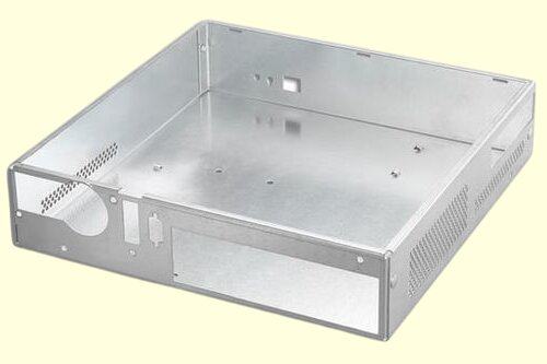
Obudowy serwerowe i komputerowe
Systemy te generują stałe i skoncentrowane ciepło. Wymagają stałego i stabilnego przepływu powietrza.
- W miarę możliwości należy stosować przepływ powietrza od przodu do tyłu.
- Umieść otwory wentylacyjne o wysokim przepływie zarówno na wlocie, jak i wylocie.
- Oddzielne strefy przepływu powietrza dla CPU/GPU i zasilacza.
- Dodaj kanały lub ścianki działowe, aby przepchnąć powietrze przez najgorętsze obszary.
- Unikaj bocznych otworów wentylacyjnych, chyba że ścieżka przepływu powietrza jest w pełni kontrolowana.
Taka konfiguracja utrzymuje stałą temperaturę i zmniejsza prawdopodobieństwo recyrkulacji gorącego powietrza w obudowie.
Przemysłowe szafy sterownicze
Szafy te często zawierają wiązki przewodów i mieszane moduły zasilania. Przepływ powietrza musi unikać przeszkód i chronić przed kurzem.
- Należy używać bocznych wlotów filtrowanych z górnymi otworami wylotowymi.
- Okablowanie należy trzymać z dala od otworów wentylacyjnych, aby uniknąć blokowania przepływu powietrza.
- W celu ochrony przed kurzem należy używać żaluzji skierowanych w dół.
- Oddzielić elementy o wysokiej temperaturze, takie jak transformatory, od elektroniki sterującej.
Filtry chronią podzespoły, ale także ograniczają przepływ powietrza, więc obszary wlotowe zwykle muszą być większe.
Obudowy zewnętrzne (Telecom, IoT, Solar)
Skrzynki zewnętrzne są narażone na działanie wysokich temperatur otoczenia, światła słonecznego i warunków pogodowych. Wentylacja musi równoważyć przepływ powietrza i ochronę.
- Unikaj górnych otworów wentylacyjnych; używaj żaluzji skierowanych w dół lub otworów labiryntowych.
- Rozważ oddychające membrany wentylacyjne zapewniające odporność na zachlapanie.
- Dodaj wewnętrzne osłony, aby ograniczyć zyski ciepła słonecznego.
- Używaj wykończeń odpornych na korozję, aby zapewnić długoterminową trwałość.
Wentylator wyzwalany temperaturą może pomóc w zarządzaniu skokami temperatury, gdy wentylacja pasywna jest niewystarczająca.
Instrumenty kompaktowe i urządzenia konsumenckie
Małe urządzenia mają ograniczoną przestrzeń i większe wymagania projektowe. Przepływ powietrza musi pozostać efektywny bez negatywnego wpływu na wygląd.
- Używaj czystych wzorów szczelin, które są zgodne z projektem produktu.
- Dodaj małe kanały powietrzne lub kanały wewnątrz, aby kierować przepływem.
- Używaj wentylatorów o niskiej prędkości obrotowej, aby zminimalizować hałas.
- Otwory wylotowe należy trzymać z dala od powierzchni dotykanych przez użytkownika.
Kierowany przepływ powietrza w ciasnych przestrzeniach zapobiega gromadzeniu się ciepła w pobliżu wrażliwych komponentów.
Wnioski
Dobra wentylacja wymaga starannego planowania. Każda metoda - wycięcia, żaluzje, perforowane panele, wentylatory lub kanały - zmienia sposób, w jaki ciepło przemieszcza się wewnątrz obudowy. Wybór materiału, kształt otworu wentylacyjnego, kierunek przepływu powietrza i ograniczenia środowiskowe wpływają na to, jak dobrze system utrzymuje chłód i stabilność.
Jeśli projektujesz obudowę i potrzebujesz niezawodnego planu wentylacji, możemy Ci pomóc. Prosimy o przesłanie plików 3D, szczegółów obciążenia cieplnego lub przykładowych rysunków. Zapewnimy szybką i praktyczną ocenę przepływu powietrza i zalecimy odpowiednie style wentylacji. Możemy również porównać opcje kosztowe i pomóc w stworzeniu chłodniejszego, bezpieczniejszego i gotowego do produkcji projektu.
Hej, jestem Kevin Lee

Przez ostatnie 10 lat byłem zanurzony w różnych formach produkcji blach, dzieląc się tutaj fajnymi spostrzeżeniami z moich doświadczeń w różnych warsztatach.
Skontaktuj się z nami
Kevin Lee
Mam ponad dziesięcioletnie doświadczenie zawodowe w produkcji blach, specjalizując się w cięciu laserowym, gięciu, spawaniu i technikach obróbki powierzchni. Jako dyrektor techniczny w Shengen, jestem zaangażowany w rozwiązywanie złożonych wyzwań produkcyjnych i napędzanie innowacji i jakości w każdym projekcie.
Powiązane zasoby

Teksturowanie laserowe metali: przygotowanie, projektowanie pod kątem produkcji (DFM) i kontrola kosztów

Stal ocynkowana elektrolitycznie: Przewodnik po obróbce i doborze

