Het is een scenario waar elke werktuigbouwkundige en productontwerper wel eens mee te maken krijgt. Je ontwerpt een compacte plaatstalen behuizing in CAD. Het model ziet er nauwkeurig uit, de interferentiedetectie is geslaagd en het vlakke patroon wordt foutloos gegenereerd. Je stuurt de DXF naar de werkplaats en verwacht een snelle doorlooptijd.
In plaats daarvan ontvang je een "No-Quote" of een verzoek om een ontwerpwijziging (ECN). De feedback is eenvoudig maar frustrerend: "De flens op deze rand is te kort om te vormen."
In de digitale wereld van SolidWorks of Inventor wordt plaatmetaal behandeld als een materiaal met oneindige stijfheid en geen productiebeperkingen. In de fysieke wereld is het vormen van metaal echter een gewelddadig proces dat wordt bepaald door wrijving, hefboomwerking en gereedschapgeometrie.
Deze gids is bedoeld om die kloof te overbruggen. We ontmantelen de tegenstrijdige "vuistregels" - variërend van de agressieve 1,5x dikte tot de conservatieve 4x dikte - en helpen je de exacte minimale flenslengte te bepalen die nodig is voor een betrouwbare productie.
De "minimale flenslengte" definiëren
Voordat we in het mechanisme duiken, moeten we afstemmen op de definitie om dure communicatiefouten te voorkomen.
Wanneer fabrikanten het hebben over de minimale flenslengte (Lₘᵢₙ), bedoelen ze de externe afmeting van de flens - van de buitenkant van de bocht tot de rand van het onderdeel. Deze meting omvat zowel de Krommingsstraal (R) en de materiaaldikte (T).
Als deze afstand onvoldoende is, kan de afkantpers de geometrie niet fysiek creëren zonder dat dit resulteert in afvalproducten.
De fysica: Waarom de limiet bestaat?
Om te begrijpen waarom er een minimumlengte bestaat, moeten we kijken naar het standaard fabricageproces dat wordt gebruikt bij 90% precisievervaardiging: Luchtbuigen.
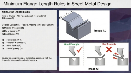
Bij luchtbuigen wordt het plaatmetaal bovenop een ondermatrijs geplaatst, die meestal een V-vormige opening heeft. Een bovenstempel daalt neer en duwt het metaal in de V-opening. Cruciaal is dat het metaal niet helemaal tot op de bodem van de matrijs wordt gedrukt. In plaats daarvan "zweeft" het op drie verschillende contactpunten:
- Het topje van de punch.
- De linkerschouder van de V-die.
- De rechterschouder van de V-die.
De "brug"-analogie
Zie het plaatwerk als een brug die een ravijn overspant (de V-opening). De brug houdt alleen stand als hij stevig op vaste grond rust aan beide kanten van de kloof.
Als je een te korte flens ontwerpt, zal het materiaal aan één kant de "schouder" van de V-die niet bereiken. In plaats van te buigen, zal de plaat gewoon in de matrijsholte glijden. Dit leidt tot drie verschillende fouten:
- Slippen en vervorming: Het onderdeel schuift zijwaarts tijdens de perscyclus, waardoor een kromme of "hondenpoot" buiglijn ontstaat.
- Guts: De wegglijdende plaat graaft in het dure geharde staal van de matrijzenschouders, waardoor het gereedschap beschadigd raakt.
- Het falen van de achteraanslag: Dit is het punt dat ontwerpers vaak over het hoofd zien. Persoperators gebruiken een achteraanslag (robotvingers achter de machine) om het onderdeel nauwkeurig te positioneren. Als de flens te kort is, kan hij de vingers van de achteraanslag niet bereiken. Zonder deze fysieke aanslag moet de operator het onderdeel op het oog positioneren, waardoor consistente massaproductie onmogelijk wordt.
De kritieke variabele: Matrijsbreedte
De breedte van de V-die opening is niet willekeurig; deze wordt gekozen op basis van de materiaaldikte (T).
De standaard industriepraktijk schrijft voor dat de V-die opening meestal 6 tot 8 keer de materiaaldikte is.
- Voor een 2,0 mm dikke plaat zal de winkel waarschijnlijk een 12 mm of 16 mm brede V-die gebruiken.
- Voor een succesvolle bocht moet de flens lang genoeg zijn om ten minste de helft van die V-opening (V/2) te overspannen, plus een veiligheidsmarge.
Deze geometrische relatie - tussen de dikte van je materiaal en de breedte van het gereedschap dat nodig is om het te buigen - is de basis voor elke minimale flensformule. Het verklaart waarom een flens van 3 mm perfect werkt op dun gauge.

De botsing van formules: Conservatief vs. Theoretisch
Als je zoekt naar minimale flensregels in technische handboeken versus productierichtlijnen, zul je een verwarrende discrepantie vinden. Sommige bronnen beweren dat je een flens kunt krijgen die maar 1,5 keer zo dik is als het materiaal (1,5T). Ondertussen staat je fabrikant waarschijnlijk op 4 keer de dikte (4T).
Waarom is er zo'n enorme kloof? Het antwoord ligt in de specifieke buigmethode die is gebruikt: Luchtbuigen versus Bottoming. Het begrijpen van dit onderscheid is de sleutel tot het ontwerpen van onderdelen die niet alleen mogelijk, maar ook economisch zijn.
1. De "Veilige Fabrikant"-benadering (De 4T-regel)
Als je ontwerpt voor algemene productie en er zeker van wilt zijn dat je onderdelen snel worden genoteerd en zonder defecten worden gemaakt, dan is dit de regel die je moet volgen.
De formule:
Lₘᵢₙ ≈ 4 × T + R
(Waarbij T = materiaaldikte en R = buigradius)
De productierealiteit:
Deze formule is afgeleid van Air Bending, de industriestandaard voor modern precisie plaatwerk.
- V-vorm breedte: Zoals vastgesteld, wordt voor luchtbuigen een V-die breedte van ruwweg 6T tot 8T gebruikt.
- De geometrie: Om de helft van die V-opening veilig te overbruggen, moet het materiaal ruwweg 3T tot 4T vanuit het midden uitsteken.
- De veiligheidsfactor: Het toevoegen van de buigradius (R) aan de formule zorgt ervoor dat zelfs als het metaal krult en lengte verbruikt, het stevig op de schouders van de matrijs blijft liggen.
Waarom slimme ingenieurs het gebruiken:
Ontwerpen met de 4T regel geeft de werkvloer flexibiliteit. Zo kunnen ze een standaardreeks V-dies gebruiken die beschikbaar is op elke machine.
- Scenario: Als je tot de absolute limiet ontwerpt (1,5T) en het specifieke tight-V gereedschap van de werkplaats is beschadigd of voert op dat moment een andere opdracht uit, dan stopt je productie.
- Scenario: Als u ontwerpt naar 4T, kan de operator indien nodig overschakelen naar een iets bredere matrijs om de productie op gang te houden, zodat uw doorlooptijd gewaarborgd blijft.
2. De "theoretische" benadering (de 1,5T-regel)
Als je technische referentieteksten zoals de Machinehandboek of specifieke gereedschapscatalogi bekijkt, zie je vaak veel kortere waarden.
De formule:
Lₘᵢₙ ≈ 1,5 × T tot 2,0 × T
De verborgen kosten:
Deze regel is typisch van toepassing op Bottoming (of Coining), niet op standaard luchtbuigen. Bij 'bottoming' drukt de pons de plaat helemaal naar de bodem van de V-matrijs, waardoor de materiaalstructuur wordt vastgeklemd. Omdat de plaat fysiek geklemd zit tussen de pons en de matrijs, hoeft hij niet de volledige breedte van de V-opening te overbruggen om stabiel te blijven.
Vertrouwen op deze regel brengt echter aanzienlijke risico's en kosten met zich mee:
- Tonnage pieken: Voor afkanten is tot 5 keer de tonnage van luchtbuigen nodig. Veel elektrische of hybride precisieafkantpersen zijn niet ontworpen voor deze aanhoudende hoge belasting.
- Slijtage van gereedschap: De hoge druk versnelt de slijtage van de stempel en matrijs, wat leidt tot inconsistente hoeken na verloop van tijd.
- Procesincompatibiliteit: Als een winkel je 1,5T ontwerp probeert te buigen omdat ze niet genoeg tonnage hebben om het te buigen, zal het onderdeel falen. Het zal in de matrijs glijden, wat resulteert in een afgedankte batch.
De uitspraak
De "1.5T Regel" is theoretisch mogelijk maar operationeel duur en riskant. De "4T-regel" is conservatief, betrouwbaar en goedkoop.
De Gouden Regel van DFM:
Ontwerp waar mogelijk altijd volgens de conservatieve regel (4T). Gebruik de theoretische limiet (1,5T) alleen als het ontwerp daar absoluut om vraagt en wees voorbereid op mogelijke tegenwerking of hogere gereedschapskosten van uw leverancier.
Het buigen van het buigbare: Variabelen en oplossingen
Voordat je kiest voor een korte flens, moet je begrijpen hoe materiaalkeuze en buighoeken de doelpalen verschuiven van wat fysiek mogelijk is.
De materiaalfactor: Waarom cijfers ertoe doen
Niet alle metalen gedragen zich hetzelfde onder de pers. De minimale lengte van de flens is direct gekoppeld aan de vereiste buigradius (R) en de radius wordt bepaald door de vervormbaarheid van het materiaal.
- Aluminium 6061-T6 (De broze uitdaging): Deze gangbare ruimtevaartkwaliteit is berucht om zijn broosheid. Als je het scherp probeert te buigen, zal het barsten. Om dit te voorkomen, moeten fabrikanten een grotere buigradius gebruiken (vaak 1,5T of meer). Aangezien onze formule Lₘᵢₙ = 4T + R is, vraagt een grotere radius automatisch om een langere flens.
- Aluminium 5052-H32 (het buigzame alternatief): Als je ontwerp een krappe flens vereist, overweeg dan om over te schakelen op 5052. Dit is zachter en kan een strakkere radius aan zonder te barsten, waardoor de minimale lengte van de flens korter is.
- Roestvrij staal: Vanwege de hoge vloeigrens en de aanzienlijke "terugvering" moet roestvast staal vaak worden overgebogen om de uiteindelijke hoek te bereiken. Deze diepere slag kan een bredere V-die vereisen om de tonnagelimieten van het gereedschap niet te overschrijden, waardoor de vereiste flenslengte toeneemt.
De hoekfactor
De meeste ontwerpgidsen gaan uit van een standaardbocht van 90°. De buighoek verandert de fysica van de contactpunten van de V-matrijs echter aanzienlijk.
- Scherpe hoeken (<90°): Om metaal tot 30° of 45° te buigen, moet de pons dieper in de V-die gaan. Deze diepere slag trekt de plaat verder weg van de schouders van de matrijs. Bij scherpe bochten zijn daarom vaak langere flenzen nodig dan bij 90° bochten om ervoor te zorgen dat het materiaal tijdens de hele slag contact houdt met de matrijs.
- stompe hoeken (>90°): Deze zijn over het algemeen veiliger. De pons legt minder afstand af, dus het risico dat de flens in de matrijs glijdt is kleiner.
De "cheatcodes": Hoe het onmogelijke te fabriceren
Wat gebeurt er als je een 2,0 mm dik chassis hebt en je absoluut moet een flens van 3,0 mm hebben om een onderdeel vrij te maken? Het standaard luchtbuigproces zegt "Onmogelijk".
Een bekwame productiepartner kan deze geometrie echter wel realiseren, als je bereid bent ervoor te betalen. Hier zijn de drie meest voorkomende workarounds.
1. De "buig- en knipmethode
Dit is de brute oplossing voor prototypes en precisieonderdelen in kleine aantallen.
- Het proces: De werkplaats lasersnijdt het vlakke patroon met een flens die veilig lang is (bijvoorbeeld 10 mm). Ze buigen het normaal met standaardgereedschap. Daarna gaat het onderdeel naar een CNC-frees waar het overtollige materiaal wordt bewerkt tot de gewenste lengte van 3,0 mm.
- De kosten: Hoog. Je voegt een secundaire bewerkingsopstelling, handmatige verwerking en ontbraamstappen toe. U moet zich afvragen: Is die korte flens een verhoging van de eenheidskosten van 200% tot 300% waard?
2. Ontlastingsinkepingen
Soms lijkt een flens alleen te kort omdat hij grenst aan een uitsparing of een afgeschuinde hoek.
- De oplossing: Voeg een reliëfinkeping toe (een kleine snede loodrecht op de buiglijn) op het overgangspunt. Dit scheidt de flens die je buigt fysiek van de problematische geometrie in de buurt. Hierdoor kan de flens onafhankelijk vervormen zonder het materiaal te scheuren of zonder dat de operator een complexe, niet-lineaire rand moet uitlijnen tegen de achteraanslag.
3. Strategie voor gespecialiseerde gereedschappen
Als "Buigen en Snijden" te duur is voor massaproductie, kun je gespecialiseerde gereedschapsopties bespreken met je fabrikant:
- Roterende buigmachines / reinigingsmatrijzen: In tegenstelling tot standaard V-dies houden deze gereedschappen het onderdeel vlak en "vegen" ze de flens omhoog met behulp van een roterende nok. Ze kunnen flenzen vormen met een dikte tot 1 × de dikte zonder te slippen.
- Offset matrijzen: Dit zijn specifieke gereedschappen die ontworpen zijn om twee bochten (een "Z"-vorm) in één slag te maken. Ze zijn uitstekend voor korte offsets, maar vereisen specifiek gereedschap voor elke specifieke hoogte.
Het spiekbriefje en de laatste checklist
Laten we al die theorie nu eens samenvatten in iets wat je direct kunt gebruiken: een snel-reference spiekbriefje en een laatste DFM (Design for Manufacturing) checklist die je kunt uitvoeren voordat je je tekeningen vrijgeeft.
Snelle referentiegegevenstabel
In de tabel hieronder worden de "Veilige" waarden (luchtbuigen) afgezet tegen de "Agressieve" waarden (Bottoming/Special Tooling).
- Standaard: Gebruik deze waarden voor standaardontwerpen om de laagste kosten, snelste levertijd en de mogelijkheid van meerdere bronnen te garanderen.
- Risico: Gebruik deze waarden alleen als er weinig ruimte is. Waarschuwing: Deze vereisen meestal specifiek gereedschap, een hogere tonnage of een secundaire bewerking.
| Materiaaldikte (T) | Conservatief minimum (4T+R) | Agressief minimum (1.5T-2T) |
|---|---|---|
| 0,5 mm (24-26 ga) | ~ 2,5 mm | ~ 1,0 mm |
| 1,0 mm (20 ga) | ~ 5,0 mm | ~ 2,0 mm |
| 1,5 mm (16 ga) | ~ 7,0 mm | ~ 3,0 mm |
| 2,0 mm (14 ga) | ~ 9,0 mm | ~ 4,0 mm |
| 3,0 mm (11 ga) | ~ 13,0 mm | ~ 5,0 mm |
> Technische opmerking: De "conservatieve" waarden gaan uit van een standaard buigradius (R) die ongeveer gelijk is aan de materiaaldikte. Als je een grotere radius opgeeft (bijvoorbeeld R=3mm op 1mm materiaal), moet je die extra lengte toevoegen aan je minimale flens.
Je laatste DFM-checklist
Voordat je op "Vrijgeven" drukt bij die laatste CAD-revisie, moet je eerst deze vijf vragen stellen. Ze besparen u uren heen en weer gemail met uw fabrikant en mogelijk duizenden dollars aan afval.
1. Welke regel heb ik gevolgd?
- Als je flens > 4 × T is, ben je veilig. Ga vol vertrouwen verder.
- Als je flens < 2,5 × T is, bevind je je in de gevarenzone. Markeer deze functie voor herziening.
2. Is de "korte flens" nodig?
- Vraag jezelf eens af: Moet deze flens echt 3 mm lang zijn? Vaak maken ontwerpers flenzen kort voor het esthetische doel of om ze "compacter" te maken. Als je de flens kunt verlengen om aan de 4T-regel te voldoen zonder andere componenten te hinderen, doe het dan. Het kost niets in het ontwerp maar bespaart geld in de productie.
3. Kan ik afwijkingen accepteren?
- De tolerantieval: Korte flenzen "zweven" meer tijdens het buigen omdat ze minder contactoppervlak hebben met de matrijs. Als je een 1,5T flens forceert, verwacht dan geen standaard hoektolerantie van ± 1. Het kan zijn dat je die tolerantie moet openen naar ± 3 om rekening te houden met de instabiliteit.
4. Heb ik rekening gehouden met de straal?
- Vergeet niet dat de effectieve flenslengte inclusief de buigradius is. Als je een flens van 10 mm hebt maar een radius van 5 mm, dan heb je nog maar 5 mm "vlak" materiaal over om vast te pakken. Zorg ervoor dat de radius is opgenomen in de berekening.
5. Ben ik bereid te betalen voor de oplossing?
- Als je absoluut een flens moet hebben die de regels overtreedt, ben je dan voorbereid op de kosten van "buigen en snijden"? Deze secundaire bewerking kan de stuksprijs verdubbelen. Als het budget krap is, herontwerp de functie dan nu.
Conclusie
In de wereld van plaatontwerp wordt het gat tussen "theoretisch mogelijk" en "economisch haalbaar" vaak gemeten in millimeters. Engineeringhandboeken vertellen je misschien dat een minimale flenslengte van 1,5x de materiaaldikte mogelijk is, maar de realiteit van de fabrieksvloer vereist meestal een veiligere 4x de dikte.
Is je ontwerp klaar voor productie? Gok niet. Ben je bang dat je krappe flenzen problemen kunnen veroorzaken op de afkantpers? Stop met gissen en begin met valideren. Stuur ons je CAD-bestanden voor een gratis DFM Review.
Hey, ik ben Kevin Lee

De afgelopen 10 jaar heb ik me verdiept in verschillende vormen van plaatbewerking en ik deel hier de coole inzichten die ik heb opgedaan in verschillende werkplaatsen.
Neem contact op
Kevin Lee
Ik heb meer dan tien jaar professionele ervaring in plaatbewerking, gespecialiseerd in lasersnijden, buigen, lassen en oppervlaktebehandelingstechnieken. Als technisch directeur bij Shengen zet ik me in om complexe productie-uitdagingen op te lossen en innovatie en kwaliteit in elk project te stimuleren.
Verwante bron

Elektrolytisch verzinkt staal: handleiding voor verwerking en selectie


Vijlbewerking: Wat bepaalt de kosten en de kwaliteit van onderdelen?
